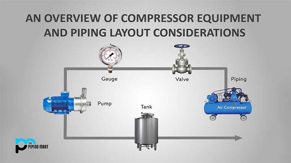
Compressor Equipment:
By mechanically reducing the volume of the gas inside the compressor’s casing, compressors are devices that are used to raise the pressure of a gas. Electric motors, diesel engines, gas-fired engines, steam turbines, and gas turbines can all be used to power compressors. The most prevalent compressors used in the oil and gas sector are those powered by gas turbines. Compressors can be either single- or multistage when a high compression ratio is needed. Intake separators, various inlet scrubbers, knockout drums, exchangers, discharge scrubbers, and seal oil systems are other pieces of equipment used in compression facilities.
What are the different Compressor Types and their layouts?
A process plant’s compressor layout must be optimized for optimal operating, maintenance, and construction needs. Gases are compressed to high pressures using compressors. This is accomplished by mechanically decreasing the volume of gas inside a compressor’s case. High pressures are necessary for different reasons, such as specific chemical reaction requirements or to condense the gas, such as LPG, LNG, etc. Different compressors are utilized depending on the type of gas to be compressed, the necessary pressure, economy, and availability.
The most common compressed gas is air, but other gases like oxygen and nitrogen can also be compressed. The three most prevalent types of compressors used in processing facilities and pipeline stations are axial, centrifugal, and positive displacement. They feature a range of drivers, including electric motors and steam or gas turbines, and can handle vast amounts of gas in relatively compact equipment.
The types of compressors are:
-
Positive Displacement Compressors:
“positive displacement compressors” refers to a broad range of air compressors that produce power by air displacement. Although the interior workings of the air compressors in this category vary, the basic idea is the same for all of them. The air from the outside is first stored in a chamber inside the machine, which gently compresses to raise the air pressure and potential energy.
-
Reciprocating compressor:
The only compressors capable of compressing gas to exceptionally high pressures are reciprocating compressors, typical of the reciprocating piston type. A crankshaft drives the pistons in reciprocating compressors. They can be single or multistaged, stationary or portable, and powered by internal combustion engines or electric motors.
Small reciprocating compressors with intermittent duty that range in horsepower from 5 to 30 are frequently used in automotive applications. Large industrial and petroleum applications frequently use reciprocating compressors with capacities far above 1,000 horsepower (750 kW). Low to extremely high discharge pressures (>18000 psi or 180 MPa) are possible. Multistage double-acting compressors, often larger and more expensive than comparable rotary units, are believed to be the most efficient compressors currently on the market for particular applications, such as air compression.
The swash plate compressor is another reciprocating compressor that uses pistons pushed by a swash plate positioned on a shaft. Smaller reciprocating compressors with an attached receiver tank are often used in homes, small workshops, and on construction sites.
-
Rotary Screw Compressors:
Rotary screws, a typical displacement compressor, are among the simplest air compressors to maintain because they include an internal cooling system that doesn’t need any upkeep. These are often enormous industrial-sized machinery that can function with or without oil.
Rotary screw air compressors use two internal, counter-rotating rotors to generate energy. The air becomes trapped between two opposing rotors, creating pressure inside the housing. These air compressors, which have a power range of 5 to 350 horsepower, are made for continuous usage thanks to their inbuilt cooling system.
-
Centrifugal compressors:
To create potential energy, centrifugal air compressors chill and gradually slow the incoming air as it passes through a diffuser. Centrifugal compressors may generate a large quantity of energy in a comparatively small machine because of their multi-phase compression process.
These compressors require less upkeep than the rotary screw or reciprocating models, and some can even create air without oil. Centrifugal compressors are often utilized for more demanding construction sites like chemical industries and steel production facilities since they can produce up to 1,000 horsepower. Large-scale steel, along with chemical industrial facilities, is ideal.
-
Dynamic Compressors:
By drawing in the air with quickly spinning blades and constricting it to create pressure, dynamic air compressors produce horsepower. The kinetic energy is subsequently statically stored by the compressor. Axial and centrifugal compressors are the two most common types of dynamic compressors
-
Axial Compressors:
Construction projects do not frequently use axial air compressors. They are typically found in the powerful engines of various ships and aircraft. Due to their high cost and high-efficiency rate compared to other air compressors, axial compressors are most frequently utilized in aeronautical applications. It is proven to be best for shipboard high-speed engines and aerospace applications.
The layout of Compressor Equipment:
It is best to place compressors that handle hydrocarbon gases out in the open to benefit from natural ventilation and lessen the chance of hydrocarbons building up there. Compressors should be placed close to critical roadways outdoors so that mobile equipment can be easily handled and maintained. If housing for the compressors is necessary, the structure must have enough ventilation.
Ventilation should ensure that there is no risk to workers in various operating circumstances, including unforeseen ones such as gasket blowouts or packing gland leaks, which can lead to the buildup of dangerous concentrations of toxic or combustible gases. Firefighting supplies must be accessible to the compressor shelter from two different directions. Compressors inside buildings must have access to an overhead traveling crane to make maintenance easier.
Ample laydown facilities and drop zones must be provided for handling big compressor components during maintenance or replacement. The size of the maintenance drop zones must allow heavy-duty trucks or trailers to access the structure and transport the compressor’s heaviest removable component. Local laydown sites must be set aside for equipment in-situ maintenance. To ensure there are no impediments, drop zones near the equipment, and the drop zones at the transportation locations must be marked on the layout.
Compressors in flammable service are considered potential sources of dangers and hydrocarbon inventory. They must be placed away and downwind from potential ignition sources such as heaters and non-certified electrical equipment (recommended minimum 15m clearance).
Building and operating platforms must have two diagonally opposed escape routes. At least one major exit from the operating platform must be through stairs, and a secondary escape may be via a fixed cage ladder. At most, the maximum distance from any location to the building or operational platform exit must be the distance specified in the document outlining the project’s safety philosophy. A maximum distance of 25m is advised without any rules.
Manufacturer’s recommendations must be followed for compressor layout and the area needed for operation and maintenance. There must be enough access for valves needing frequent access, and equipment needs frequent monitoring. The compressor rotor and driver must have enough room for maintenance and inspection.
Elevated should support bottom-nozzle compressors. If a compressor has top suction and discharge lines, the piping architecture must guarantee enough overhead clearances for maintenance needs. If necessary, removable spool sections must be offered to make maintenance easier. Space requirements for lubricating oil and seal oil systems must be considered when designing compressor buildings or shelters.
Centrifugal compressors with horizontally split casings must provide access from both sides for maintenance. Centrifugal compressors featuring vertically split casings must have access for maintenance opposite the drive end so the rotor can be cleaned. Since compressors present considerable risk, no equipment should be placed directly above them. The compressor must be as close as possible to the suction knockout drum. The dimension of the foundations may determine the distance between two neighboring massive, heavy-duty compressors.
Piping Layout for centrifugal compressors:
Vibration and noise must be kept to a minimum while designing piping. Suction piping must be built with the minimum straight lengths the manufacturer recommends available up to the suction nozzle inlet. There shouldn’t be any constraints or obstacles in the suction piping caused by things like thermowells, flow elements, etc. There must be no pockets in the suction piping between the compressor inlet nozzle and the knockout drum. In addition, the suction line needs to slope in the direction of the knockout drum. A drainage system must be included when designing without pockets is not an option due to other layout restrictions. If chosen, top inlet compressors can remove low points.
When numerous compressors work simultaneously, the pipework must be built out symmetrically to provide an even fluid flow. The piping for centrifugal compressors must be sized to reduce noise, vibration, and pulsation. The manufacturer’s specified nozzle loadings must not be exceeded while designing the piping. Compressor piping, including lubricating and seal oil piping, must not block operation, inspection, or maintenance. The manufacturer’s recommendations should be followed regarding the minimum operating and maintenance clearances surrounding compressors for mechanical handling of casings, rotors, gearboxes, drivers, etc. Removable spool components must be offered were disassembling the entire piping is necessary for maintenance to facilitate maintenance access.
Temporary strainers must be placed to prevent harm to the compressor from foreign solids entering the suction line. These strainers must be removed before starting up and are primarily needed during pre-commissioning. The discharge nozzle and the strainer must be as close as feasible to each other. The temporary strainer should be replaced, so the suction piping construction should provide for a spool piece.
According to vendor guidelines, a temporary strainer should be installed. Typically, 1.5 to 2.0 times the cross-sectional area of the suction piping will be the optimum open area of the strainer. All strainer screens must be strong enough to keep debris from falling through and entering the compressor.
Lube and seal oil consoles must be placed close to the compressor to reduce piping to and from the compressor. Return oil lines to the consoles should be constructed so that they may self-drain. Because piping connected to compressors is vulnerable to fatigue failure from vibration, care must be taken during design and construction to rule out the possibility completely.
On the final hook-up spools connected to the compressor nozzles, there must be enough field welds and over lengths (fabrication allowances) provided during the fabrication and installation stage to ensure proper fit-up without putting additional strain on the machine and to facilitate proper machine alignment.
Piping Layout of Reciprocating Compressors:
Pressure pulses produced by reciprocating compressors can cause excessive vibration in pipe systems. Pulsation, vibration, and noise must be kept to a minimum in the design of the pipes for reciprocating compressors. It may be possible to add shock-absorbing supports to bring vibration down to a manageable level. Pulsation dampers must be installed on reciprocating compressors. Another factor contributing to flow-induced vibration in the discharge line is high gas velocities. Eliminating any flow-induced vibrations shall be the main objective of piping design.
It is necessary to leave enough room for the compressor’s pistons to be removed. Additionally, enough room must be available for big lifts, such as removing a motor, rotor, or casing. Small bore branches should not be near vibrating sources or downstream of reciprocating compressors to exclude the danger of fatigue failure due to vibration. It is advised to do so.
Establish guidelines and put their suggestions into practice, such as bracing small bore branches to lessen the possibility of failure owing to fatigue. Upstream of the first discharge isolation valve, relief valves must be installed to prevent the compressor from an excessive buildup of pressure. If it is necessary to transport the compressed discharge from relief valves back to the suction line, it must be cooled because it will be at a greater temperature.
The check valves installed in the discharge pipes for reciprocating compressors must be able to handle pulsing flow conditions. A disc-type check valve has been proposed as a quick-response check valve. To lessen potential harm to the compressor during surging conditions and prevent backflow during an emergency, the valve must be located as near as feasible to the nozzle. If necessary, anti-surge valves must be placed as near as feasible to the compressor discharge.
A pulsation study of the piping system connected to the reciprocating compressors is advised. To reduce vibrations, the suction and discharge pipework linked to reciprocating compressors must be laid close to the ground and fastened or held down when necessary. To avoid resonance effects, piping supports must be positioned at irregular intervals. Compressor piping must be placed on separate foundations and be free of the shelter to stop vibrations from being transmitted to the structure.
To prevent acoustic resonances, which can cause excessive vibration and stress in the piping system, an acoustic and mechanical analysis in compliance with API 618 must be carried out. The interstage lines must have a pressure-temperature rating equal to the discharge line if the compression is done in more than one stage. The manufacturer’s specified straight pipe lengths for suction and discharge must be followed during layout.
How to Choose the right type of compressor?
When selecting the appropriate air compressor for the job, there are various more elements to take into account, in addition to the power-generating mechanisms and energy output levels covered above.
Considering the air quality
The use of oil-powered air compressors in clean manufacturing facilities can be problematic. The internal mechanisms of most air compressors are lubricated with oil, and the fumes from these devices may contaminate the air, harming goods or production methods. This risk is significantly diminished by using an oil-free air compressor. Oil-free compressors are the only choice for facilities that ensure clean manufacturing while being generally more expensive. Oil may still be required to lubricate the machine, but oil-free compressors use a unique sealing system to ensure no oil enters the compressor. Oil-free compressors produce clean air and usually have lower operating costs due to less frequent component replacement.
Putting Energy Efficiency as a Priority
Investing more money upfront in a high-efficiency air compressor may be worthwhile in case anyone is working on a protracted building job. One of the following choices should be taken into account if looking for an energy-efficient air compressor:
-
Variable speed:
This type of compressor, also known as Variable Speed-Driven Compressors, lets one adjust output based on demand, saving energy and money. In contrast, the motors in fixed-speed compressors continuously turn at the same pace and call for an energy-intensive cooling-down period.
-
Natural gas:
Instead of diesel or electricity, natural gas air compressors work on the fuel. They frequently run more effectively than alternative solutions and have better heat recovery abilities than an electric compressor. A natural gas unit can be suitable if efficiency and energy conservation are considered top priorities.
Examining the portability restrictions
A portable air compressor is a fantastic choice if it is moved between locations. Small, light units can still deliver energy in a more condensed form. For smaller building jobs, portable compressors may be the best option, even if they won’t be as powerful as larger equipment. Some devices can power small airbrush painting or tire inflation tools by plugging them into a car’s power adaptor.
Determine whether further features are necessary
Anyone can employ several accessories and extra features with various air compressor types. To avoid disconnecting when switching activities, one can connect multiple types of equipment to the air compressor using couplers or air hose splitters, for instance. Thermal protection add-ons for air compressors monitor internal heating and prevent motor damage if the device is overworked.
Some air compressors operate more quietly, thanks to belt drive systems rather than direct drives. Make sure the selected air compressor is compatible with any of these extra features if the user anticipates using any of them.
If one wants to work on construction but wants to avoid committing to buying an air compressor, the individual can rent a variety of air compressors from different manufacturers. Make sure to have all the knowledge necessary to decide on the ideal option for the use, from small and portable to large-scale.
Pipingmart is B2B portal specializes in industrial, metal and piping products. Also, share latest information and news related to products, materials and different types grades to help business dealing in this industry.