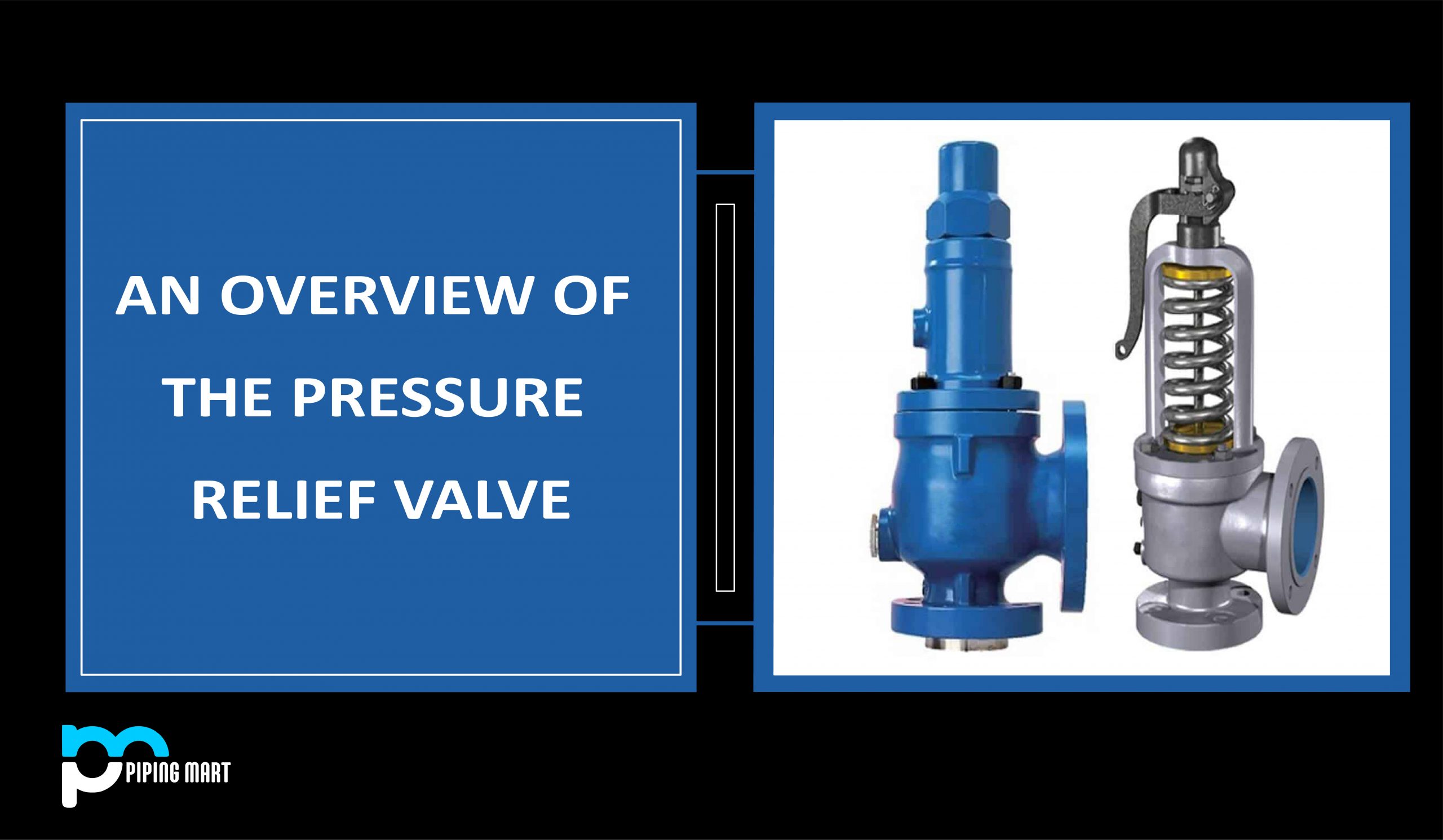
During overpressure circumstances, a pressure relief valve is utilized to release excess pressure from a system, preventing catastrophic failure. As a result, a pressure relief valve is an essential process safety equipment that is widely employed in the chemical, petrochemical, power generation, and oil and gas industries. The pressure relief valve (PRV) is designed to open when a specified set pressure is exceeded. When the system pressure exceeds the specified pressure, the PRV pops and releases the excess pressure, and the PRV closes again when the excess pressure is released.
The following are the primary benefits of putting a pressure relief valve in a system:
- They vent the fluid to protect the system from overpressure.
- They reclose and prevent fluid loss when the system pressure drops to normal levels.
- Installing the PRV system helps to keep system components in good condition.
- They are dependable and adaptable.
What are Relief Events?
Relief events are unavoidable occurrences that reduce efficiency or performance and raise costs while keeping the operating plant safe. Here are some examples of possible relief events:
- An external fire
- High-pressure flow
- Heat input from related equipment/ external source
- Failures of pumps and compressors and other equipment.
- Failure of the cooling medium
- Heat transfer in the environment
- Failure of the control system
- Pipeline liquid expansion and surge
- Blocked discharge
- Condenser system failure
- Chemical reactions
- Operating errors
- Closed Outlets
- The emergence of Volatile Fluid
Potential Lines of Defense against Relief Events
The following defense mechanisms are used to overcome the potential relief events:
- Inherently safe design
- Processes involving low pressure
- Passive Control
- Overdesign of process equipment
- Active Control
- Set up relief systems
What is a Pressure Relief System?
A relief system is an emergency device that reduces pressure or discharges gas during abnormal situations to protect plants during relief events. The relief system is made up of A relief device, as well as associated lines and process equipment, is used to safely handle the ejected material.
Why Use a Pressure Relief System?
Installing relief systems in operational facilities is required for the process and technical safety reasons.
- Inherently Safe Design cannot avoid all pressure hazards.
- Passive designs might be prohibitively costly and complex.
- Relief systems are effective
Code Requirements for Pressure relief system design
- ASME Boiler & Pressure Vessel Codes
- ASME B31.3 / Petroleum Refinery Piping
- ASME B16.5 / Flanges & Flanged Fittings
Relieving pressure shall not exceed MAWP (accumulation) by more than:
- 3% – fired and unfired steam boilers
- 10% – vessels equipped with a single pressure relief device
- 16% – vessels equipped with multiple pressure relief devices
- 21% – fire contingency
Locating Pressure Relief Valves
Process engineers choose the location of pressure relief valves. They highlight the PRV requirements in the P&ID. The following are fundamental guidelines for where relief devices are required, while there are likely to be other specific instances in any process.
- All vessels
- Blocked in heat-exposed cool liquid line sections
- Positive displacement pumps, compressors, and turbine discharge sides
- Vessel steam jackets
- Because low-pressure storage tanks are not normally intended for full vacuum, they require both vacuum and pressure release systems.
- Where formal hazard identification processes such as Hazard and Operability (HAZOP) and Process Hazard Analysis (PHA) indicates
- Piping systems in which overpressure may occur due to a process control failure.
Pressure Relief Valve Accessories
Some pressure relief valve accessories assist the valve in its operations to achieve its intended use. They are:
- During the hydrostatic test, test gags keep the safety valve closed.
- Mechanisms for lifting the valve disk. There are 3 categories available.
- Plain lever
- Packaged lever
- Air-operated lifting devices.
- In addition to screwed caps, bolted caps are available for normal pressure relief valves.
- Valve position indicators for remote PRV opening indication
Relief Valve Chattering
Chatter is the rapid opening and closing of a pressure relief valve at low flow. Under normal processing circumstances, the vessel pressure is lower than the relief valve’s specified pressure. As the pressure rises and reaches the set pressure of the relief valve, the valve opens. When the valve opens, there is flow, which causes a pressure drop between the vessel and the valve. If the pressure drop is significant enough, the pressure at the relief valve can decrease low enough to cause the relief valve to close. The flow stops, the pressure at the relief valve returns to the vessel pressure due to the lack of flow, and the relief valve reopens.
- Spring relief devices require 25-30% of full flow capacity to keep the valve seat open
- Lower flows create chattering caused by rapid opening and closing of the valve disc
- This can lead to device damage and a dangerous possible outcome
Chatter – Principal Causes
Valve Issues
- Oversized valve
- Valve handling widely differing rates
- Relief System Issues
- Excessive inlet pressure drop
- Excessive accumulated back pressure
Oversized valves will partially lift at a set pressure and then re-seat, causing “chattering” of the disc and perhaps damaging the seat/disc surfaces and causing the relief valve to fail. Installing numerous relief valves for different loads is a good practice to reduce chattering on small discharges. To prevent relief valve chattering, the line pressure drop between the equipment and the inlet of the RV during the relief case must be 3% of the RV set value.

Pipingmart is B2B portal specializes in industrial, metal and piping products. Also, share latest information and news related to products, materials and different types grades to help business dealing in this industry.
