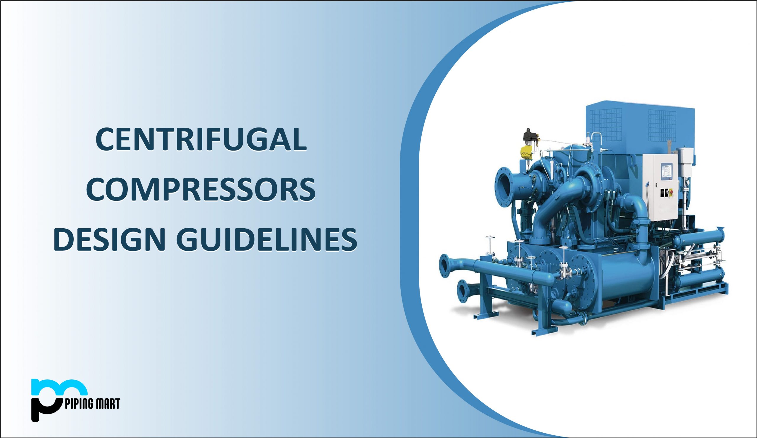
Centrifugal compressors are often known as impeller compressors or radial compressors. A centrifugal compressor is a mechanical system that compresses a fluid using the radial acceleration of the impeller, which is surrounded by the compressor housing. The gas or air enters the impeller axially and exits radially in a centrifugal compressor. As a result, it is also known as a radial compressor.
The impeller in a centrifugal compressor increases the speed of the working fluid (gas or air) by transforming the air/kinetic gas’s energy into speed. Furthermore, the diffuser turns the speed of the air or gas into pressure energy. Radial centrifugal compressors have a better high-pressure ratio at low flow rates, which gives them a significant advantage over axial compressors.
The Design Guidelines of a Centrifugal Compressor are listed below:
Design parameters: In the process industries, centrifugal compressors are designed in accordance with API 617. When it comes to designing a centrifugal compressor, the type of gas, the gas’s temperature, pressure, molecular weight, and corrosion characteristics, gas fluctuations these parameters must be taken into consideration
Flow Rates: For any impeller, a minimum flow rate of approximately 180 m3/h is considered. The efficiency of the centrifugal compressor decreases as the flow rate approaches this limit.
Application Pressure Range: There are no restrictions on lower pressures with appropriate seals. However, the use of thicker components and the number of stages in a single casing limits the maximum operating pressure (generally limited to 8). Discharge pressures for horizontally split designs are often up to 100 bar. Discharge pressures in radially split (barrel) designs can reach 800 bar. High suction pressures make sealing difficult, and the majority of applications have suction pressures of less than 200 bar.
Application Temperature Range: With proper consideration of materials that give ductility and appropriate brittle strength, the lower temperature can be as low as -750C. The materials used for sealing should be compatible. The most common higher temperature encountered is 180-1900 C. Cool buffer gas can be injected at temperatures higher up to 2300 degrees Celsius.
Number of Stages: The number of stages or impellers is determined by the compression ratio or head. A single-section centrifugal should have no more than 9 impellers per casing, and a two-section centrifugal should have no more than 8 impellers per casing. In the case of a compressor with a side stream entry, the maximum number of impellers per casing should be 7.
Rotating Speed: Higher rotative speeds result in better work per stage performance. For fully enclosed impeller designs, the impeller tip speed should generally range between 650 and 900 ft/sec (198 and 274 m/s). The maximum speed limit of an open impeller is higher due to the reduced centrifugal forces created by the absence of the cover’s mass.
Compressor Efficiencies: There are two types of compressor efficiencies used in industrial applications of centrifugal compressors, which are isentropic Efficiency and Polytropic Efficiency. Isentropic efficiency is calculated as isentropic compression work divided by actual compression work. Polytropic efficiency is widely utilized in work or power calculations for centrifugal compressors. Because the polytropic efficiency is almost proportional to the logarithm of the inlet gas volume flow rate, it may also be estimated using the inlet volume flow.
Pipingmart is B2B portal specializes in industrial, metal and piping products. Also, share latest information and news related to products, materials and different types grades to help business dealing in this industry.