The operating effectiveness and lifespan of any pump can be significantly impacted by the pump pipe design. Therefore, when developing the pump piping layout, the design engineer must consider these factors. Suction and discharge lines should be designed with the pipe system’s operability, maintainability, flexibility, and support needs in mind.
Pump cavitation, which occurs when liquid is displaced within the pump casing and causes vibrations and damage to the pump impeller, can be brought on by improperly built pump suction pipes. Here, we shall discover the many pump piping arrangement patterns and design considerations.
Essential Points to be Considered While Designing Pump Piping
- Never allow the suction pipe to be smaller than the pump’s suction nozzle. The suction nozzle is typically one size smaller.
- It is best if the suction line is short and straight.
- The suction line needs to be devoid of pockets.
- For commissioning and testing, a temporary filter of the conical type must fit into all of the pump suction lines.
- The plumbing for the suction and discharge lines needs to be supported separately from the pump foundation.
- Depending on the situation, expansion joints may be employed on either the suction or discharge line side or perhaps both. However, expansion joints should only be utilized when there is no choice because they are the last resort.
- To prevent pressure loads from being transferred to the pump nozzle when expansion joints are employed, a pipe anchor must be placed between the expansion joint and the pump nozzle.
- Preferably, the sump’s suction pipe should be horizontal and sloped toward the pump’s suction nozzle.
- There should be at least “three to five times the diameter of the suction nozzle” of straight pipe between the pump’s suction nozzle and the first elbow, flange, valve, tee, or filter when the suction pipework is horizontal. That straight length may include the reducer.
- The suction line’s mating flange and the pump’s suction nozzle should be made of the same material and rating.
- The velocity of the suction pipe should not exceed two m/s since higher velocities will result in friction loss.
- Elbows and tees shouldn’t be installed close to the pump’s suction nozzle to prevent an irregular flow pattern inside the suction line.
- The elbow should ideally be vertical if it is required at the suction line of a twin suction pump. It should be an extended radius elbow if a horizontal elbow is necessary.
- Pump piping should be constructed with enough room to remove the pump efficiently.
- Where the weight of the component exceeds 25 kilos, lifting facilities are offered. Therefore, space must be made available for mobile equipment to do maintenance without causing harm.
- As a backup pump is needed to maintain production during a primary pump maintenance window, it should be considered when constructing the pump pipes.
- If the lifting operations are impeded, the pump piping should have removable spool portions with breakup flange.
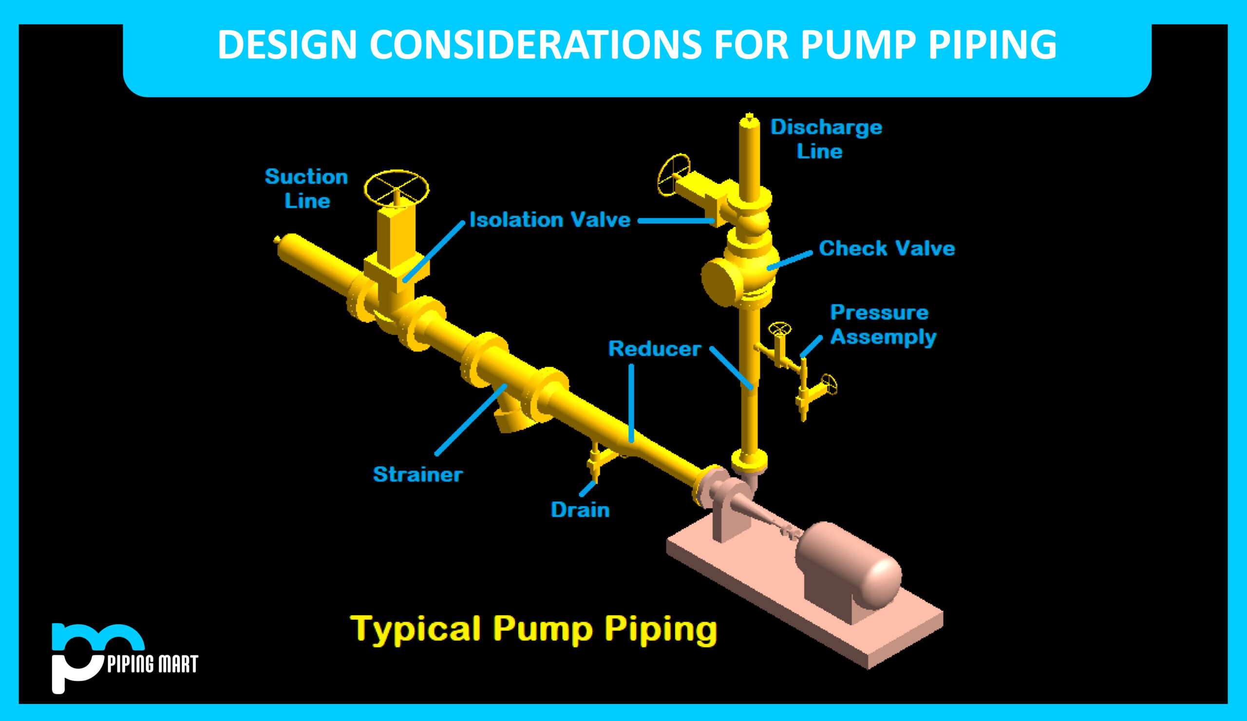
Fittings and Components Used in the Pump Discharge Line
The following are the piping fittings and parts that are most frequently used in the discharge line:
- Reducer
A concentric reducer is typically utilized in the discharge line and is kept as close to the discharge nozzle as is practical. A minimum of five times the discharge nozzle’s diameter must be maintained in the length of the straight pipe between it and the reducer. The straight length may also contain the reducer length.
The eccentric reducer can be utilized flat side down for simplicity of support if the discharge line is in a horizontal plane, as in the case of a side suction side discharge pump.
- Pressure Gauge Assembly
The pressure gauge must be placed on the discharge line before the check and isolation valve to monitor discharge pressure. The drain may also be part of the pressure gauge assembly.
- Check Valve
To prevent backflow, check valves are typically installed in the discharge line following the reducer and pressure gauge assembly. A check valve is a one-way valve that allows unrestricted flow in one direction but closes to stop backflow if the flow changes direction.
A water hammer can happen if the flow reverses and there isn’t a check valve. A water hammer can easily harm the pump and piping when it happens with a lot of power.
It can be used in horizontal and vertical lines and has a lift of up to 1 1/2 inches.
Swing-type check valves more significant than 1 1/2 inches are commonly fitted in a horizontal row. Swing check valves up to 6 inches in diameter can be installed in a vertical line if necessary. Still, check valves more significant than 6 inches should only be set in a horizontal line.
- Isolation Valve
To isolate the discharge line and to remove the check valve for maintenance, the isolation valve (often a gate valve) is fitted immediately following the check valve. Due to its frequent use, the isolation valve is installed with operability in mind.
Pump Location
Numerous factors can affect the pump’s placement. When placing the pump, the primary objective is to reduce the length of the suction piping while still meeting the need for piping flexibility and the permissible loads that will be placed on the pump nozzles. Here are some details on where the pump is located:
- In the hydrocarbon sector, pumps are frequently installed beneath the ground-level pipe rack.
- Pumps must be installed as close to the vessel or sump and below the vessels as possible to achieve the net-positive suction head (NPSH) that the pump demands.
- According to OISD-118, the pump must be kept outside the tank farm or dike wall at a minimum distance determined by the class of stored fluid.
- The minimum distance between the two pumps should be 1 meter following OISD-118.
- Standard pipe rack column spacing is 6 meters, and it is usually only possible to install a pair of average-sized pumps between two columns.
- According to engineering standards, there should be a minimum of 0.75 meters between the discharge piping and the steel structure.
- The space needed for strainer maintenance can be used to determine the centerline elevation of the pump. According to engineering standards, a 300 mm minimum space should be left between the suction line and grade level. The size of this gap varies from firm to company and is not fixed.
Pump Piping Support
To create a proper pump piping arrangement, a piping layout engineer must have a working grasp of stress and pipe supports. This will prevent the stress engineer from modifying the piping after determining that it is not stress-friendly.
If the following guidelines are followed, the designer will be able to produce pump piping that is stress-friendly:
- If the suction line has an elbow, a fake leg or trunnion can support it.
- The pipe rack steel framework, hangers, or spring supports can all be used to support the discharge line, depending on your preferences.
- The stress expansion joint can release tension in the line if there is more vibration than usual. However, this is not recommended.
- The pump foundation can be expanded to support the suction line if the pumps are situated in poor soil where differential settling may develop. Maintaining communication with the stressed civil engineer will allow for the best decision.
- The discharge line should be supported within 5D of the elbow, which is as close as practicable.
- The line can be made flexible by adjusting support if it is subject to high pressure and temperature.
- If the valve is overly heavy, resting supports can be placed on both sides.
- It is easier to support and operate both valves if the discharge line is more significant than six ′′ and is kept horizontal after the reduction.
Pipingmart is B2B portal specializes in industrial, metal and piping products. Also, share latest information and news related to products, materials and different types grades to help business dealing in this industry.