What are Valves?
A valve is a significant tool that can start, stop, mix, control, or regulate the flow or pressure of a fluid in piping systems by altering the flow of fluid via the pipe. Any piping system that transports liquids, vapors, slurries, gases, and mixes of liquid and gaseous phases of different flow media must have valves.
Generally, the piping system must include several types of valves to control the flow of fluid through it. A valve’s opening can be changed and controlled manually or with the help of an actuator. The actuator can be powered by electricity, hydraulics, or pneumatics. The valves must be carefully chosen because they account for a sizeable portion of the chemical process industry’s overall spending.
In the piping industry, valves are installed to carry out any of the following tasks:
- Regulation,
- Non-return,
- Special purpose, and
- Isolation
The performance of the process plant and its overall activity will depend on having a thorough understanding of the operation, maintenance, and valve adjustment.
The most expensive rigid piping parts in a plant are valves. They can make up as much as 20% to 30% of a process plant’s overall pipe item prices. The size of a valve’s ends that are attached to the piping system determines its size.
Typical valve types can be self-actuated, manually operated, or equipped with actuators. Valves can be operated by electric, pneumatic, hydraulic, or a combination of these actuators. According to the application, metals and non-metals are used to make valves.
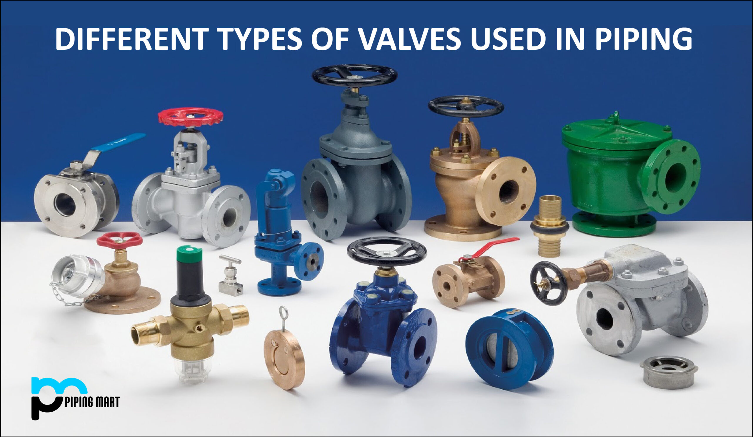
Different Types of Valves Used in Piping:
Gate Valve- The gate valve is made of a gate-like disc that slides up and down at right angles to the flow direction and is controlled by a screwed stem and handwheel. The disc shuts off the flow when it is in the closed position where it rests against two faces. Gate valves are not appropriate for throttling operations because the gate and gate seats experience severe wear due to wire drawing (erosion). They work well as stop (or isolating) valves when the situation calls for either a complete flow or none at all. They have the benefit of having little flow resistance and little pressure loss when fully opened, as the fluid flows in a straight path.
Globe Valves- The globe valve’s design necessitates two direction changes in the fluid flow that passes through it. The disc and the seat are positioned parallel to the main flow route, and a threaded stem is used to move the disc closer or away from the seat. The globe valve’s design makes it perfect for throttling or regulating flow with the least amount of wire drawing and seat erosion. The globe valve has a lower cost of production when compared to the gate valve, which is another benefit. The gate valve has far less flow resistance than the globe valve, on the other hand.
Needle Valves- It is possible to control flow precisely with needle valves. Its name comes from the seat’s matching sharp-pointed disc. They are frequently employed for chemical feed control or continuous blowoff services. A large amount of hand wheel movement is needed to change the aperture through the seat because the stem threads are smaller than typical. These valves often have a smaller seat diameter than the pipe size.
Butterfly Valves- A butterfly valve is made up of the valve body, disc, shaft, and any packing or bushings required to support the shaft. The body, which is installed between pipe flanges, is often of the solid ring type. Typically, the disc is cast in one piece. This valve must be properly positioned to avoid binding the swing-through disc. The pressure drop across the valve determines the thickness of the disc (throttling or closed position). Butterfly valves are made for pressures up to 13 800 kPa and temperatures up to 1100oC, and their sizes range from 25 to 3800 mm (1 to 152 inches). The flat disc has a 90-degree rotational range, allowing it to be moved from a completely open to a fully closed position. The valve has a manual operation lever built into it. Because there may be significant pressure differentials over a larger size disc, a power actuator is needed to position the disc. The butterfly valve is frequently used in thermal and hydroelectric power plants, the oil and gas processing and transportation sectors, as well as water and sewage treatment facilities. They are relatively lightweight, simple to use, self-cleaning, and have a minimal pressure drop across the valve when fully opened.
Ball Valves- The fluid flow through the valve body is controlled by a sphere-shaped stopper that is part of a ball valve. When switching from the fully open to the closed position, the fundamental type of ball valve requires a quarter turn. Both an automatic actuator and a lever, which also functions as an open/shut indicator, can be used to operate the valve. The spherical plug provides a tight shutdown when the valve is closed in addition to precise control of the flow through the valve. The valves’ design eliminates the need for internal lubrication and minimizes the torque needed to rotate the ball. Typically, the ball and stem are fabricated from a single piece.
The ball is built with a double stem and supported by bearings for greater sizes and higher pressure ratings. For this design, a seal is needed for one end and a box for the other. The ball valves can withstand pressures up to 69000 kPa and operating temperatures between -185°C and 550°C. They are produced in sizes ranging from 3 to 1000 mm (1/8 to 40 in.). Ball valves have many uses in the paper industry, chemical industries, and sewage treatment facilities because they are effective at managing slurries and fluids with high solid content.
Plug Valves- Butterfly and ball valves, as well as the plug valve, are quarter turn valves. A tapered or straight cylinder with a hole, which is put into the chamber of the valve body, makes up the plug valve. The axis and opening in the valve body are aligned with the hole in the plug. The valve features a tapered plug that the valve cover fastens inside the valve body. This cover has a packing box recessed into it that the gland holds in place to stop leakage along the valve stem. The tapered plug has a propensity to jam in the tapered seat and, if forced to turn, can result in scoring. The majority of plug valves are lubricated to solve this issue. Through channels, the lubricant is dispersed to the seating surfaces after being fed through the stem’s center. Some valves don’t require lubricating since they have flexible, smooth liners. When this valve is fully open, there is relatively little pressure loss across it. The valve in question is self-cleaning. In gas supply lines, low-pressure steam lines, water treatment facilities, the pulp and paper industry, and the chemical industry, plug valves are employed as quick opening valves.
Check Valves- The check valve is a valve that stops pipes from having their flow reversed. While gravity and a change in flow direction will cause the valve to close, the fluid flow keeps the check valve open. The swing check and the lift check are the two fundamental varieties of check valves. Because of its nearly straight-line flow, the swing check valve presents little flow resistance. The disc, which has a top hinge, can freely swing in an arc between the totally closed and fully open positions. As the flow passes through a horizontal part where the disc seats, the lift check valve, reverses direction twice. The disc opens by moving higher to let the fluid through and closes by moving downward if the flow should reverse. In this design, the disc’s motion is muted by a dashpot.
Different Parts of Valve:
Valve Body- The valve body, which also serves as a conduit for fluid, houses the internal components of the valve. Casting, forging, fabrication, or a combination of two or more techniques are used to make the valve body. Valve bodies can be made from a range of metals or nonmetals depending on their size, pressure-temperature rating, and service needs. The nozzles on the equipment or pipe are intended to connect with the ends of the valve body. Some valve bodies have linings made of materials that resist corrosion.
Bonnet of the Valve- The bonnet or cover, another pressure-retaining shell, is where the valve body is attached. Usually, it has a passageway for the valve stem to flow through. Often there is a stuffing compartment found inside the bonnet. The bonnet or cover provides access to the valve internals. It functions as the foundation for the valve top mechanisms, such as the yoke, hand-wheel, etc. The Bonnet is categorized based on the type of attachment as Bolted, Bellow, Sealed, Screwed-on, Welded, Union, Pressure Sealed, etc.
Cover Bolting- Bolting refers to the collective term for bolts, nuts, and washers. The application must adhere to the relevant norms and standards for the bolting material to be chosen.
Disc- One of the main parts of the valve that, depending on its position, permits, throttles, or stops the flow is the valve disc. Thus, the flow is directly impacted by the disc. It goes by many names in different valves. For instance, the disc is sometimes referred to as a plug-in-plug valve, a ball-in-ball valve, and a gate-in-gate valve.
A disc is produced through fabrication, forging, or casting. The disc is pressed up against the stationary valve seat when the valve is closed. The valve can be opened or closed by manipulating the disc in response to the movement of the valve stem.
Trim- The interior components of the valve that can be removed and changed are called valve trims. The term “valve trim” refers to all of these components that come into touch with the flow medium. These parts include internal springs, valve seats, glands, discs, spacers, guides, and bushings. Keep in mind that although coming into touch with the flow medium, the valve body, bonnet, packing, etc. are not considered to be part of the valve trim.
Seat- The disk’s seating surface is provided by the seat or seal rings. There may be one or several seats in a valve. For a globe or swing-check valve, there is often only one seat, which joins the disc in a seal to stop the flow. One seat is on the downstream side of a gate valve, and the other is on the upstream side.
Two seating surfaces on a gate valve disc make contact with the valve seats to create a seal and stop the flow. The contact surface of the seal ring is frequently hard-faced by welding and then machining to increase the wear-resistance of the seal rings.
To ensure proper sealing when the valve is closed, the sitting region must have a fine surface finish. The body has enough wall thickness to resist design pressure without depending on the thickness of the seal rings, hence seal rings are typically not considered pressure boundary sections.
Stem- The disc receives the necessary motion from the valve stem to open or close the valve. The valve handwheel, actuator, or lever is attached to one side of the stem while the valve disc is attached to the other. While plug, ball, and butterfly valves require rotation of the valve disc to open or close the valve, gate or globe valves require only linear motion of the disc. However, check valves lack valve stems (except for stop-check valves). The valve stem is divided into four kinds-
Rising Stem: The handwheel may either rise alongside the stem or independently of it.
Non-Rising Stem: Regardless of whether the valve is open or closed, the Hand Wheel and the stem are in the same position. In this scenario, the screw comes into contact with the fluid while being inside the Bonnet.
Sliding Stem- The valve stem glides in and out of the valve to open or close the valve in this variation.
Rotary Stem: The Rotary type valve stem is often used in ball, plug, and butterfly valves. Such a valve just requires a quarter-turn of the stem to open or close.
Stem Packing-
The Stem packing may do one or both of the following two tasks, depending on the application:
- Preventing outside air from accessing the valve in vacuum applications Preventing leakage of the flow medium to the environment
- The stuffing box houses the stem packing. By tightening a packing nut or packing gland bolts, packing rings are packed and crushed. For a good seal to be created, compression must be sufficient.
Yoke and Yoke Nut-
Yoke- The actuation mechanism is connected to the valve body or bonnet by a yoke. The valve stem travels through the top of the yoke, which is holding a yoke nut, stem nut, or yoke bushing. Yokes typically have access points for the stuffing box, actuator linkages, etc. A Yoke’s structural strength must be sufficient to resist the forces, moments, and torque generated by the actuator.
Yoke Nut- An internally threaded nut called a yoke nut is inserted into the top of a yoke through which the stem travels. For instance, turning the yoke nut causes the stem of a gate valve to move upward or downward. The nut is fixed and the stem is rotated via it in the case of Globe valves.
Valves Based on:
End Connection- Taking into consideration the end connection of a pipe, the valves can have the following ends: flanged ends (Often 2″ and bigger valves), butt-welded ends, screwed ends, socket welded ends, and wafer type.
Material Used in the Construction of the Valve- Different materials metals as well as non-metals can be used for construction purposes such as carbon Steel, alloy steel, iron, stainless steel, aluminum, Monel, glass, PVC, etc.
Actuator Operation-
Hand lever- A small butterfly, ball, and plug valve stems are operated by it. The operation of small plug valves is done with a wrench.
Hand Wheel- The most typical method of spinning the stem is the Handwheel for the majority of widely used smaller valves. When a simpler operation is required, impact handwheels or hammer blow handwheels might be used in place of regular handwheels.
Chain- Where a handwheel would be out of reach, a chain is employed. For lever-operated valves, the stem is supplied with a chain wheel or wrench, and the chain loop is lowered to within one meter of the working floor level.
Gear operator- They are used in lowering operating torque in gear-operated valves. In the event of a manual operator, it consists of a hand wheel-operated gear train that opens the valve stem. As a general guideline, gear operators should use valves that are at least 350 mm NB, 200 mm NB, 150 mm NB, and 100 mm NB in size or larger for higher ratings.
Pneumatic and hydraulic operators- They are utilized in circumstances where the likelihood of flammable vapor is high
Electric Geared Motor: To move the valve stem on big valves in isolated areas, an electric gear motor is employed.
Fast-acting check valves and on/off valves can both be controlled by solenoids in light-duty instrumentation applications.
Mechanical Motion-
Linear Motion: Linear motion valves allow, control, regulate, halt, or throttle the flow while the closure component moves in a straight line. A gate, globe, diaphragm, pinch, and lift check valves are all included in liner motion valves. There are two types of linear valves: rising stem (multi-turn), and axial. The flow obstructer moves linearly in both types of valves, although their design and functionality differ greatly.
The obstructer is rotated by a threaded rod (stem) attached to the obstructer in the case of multi-turn rising stem valves. Globe valves, gate valves, pinch valves, needle valves, and diaphragm valves are typical examples of multi-turn valves and are frequently employed in flow control applications.
Axial valves, on the other hand, use pneumatic or electromagnetic force to move the flow obstructer along an axis. These kinds of valves, which are often fast-acting and only employed for on/off process applications, include coaxial valves, angle seat valves, etc.
Rotary Motion Valves: The valve-closure member moves in an angular or circular motion in butterfly, ball, plug, eccentric, and swing check valves. Because they rely on the rotational motion of the flow obstructer, these kinds of valves are also known as rotary motion valves. Typically, just a quarter turn or 90 degrees can be rotated.
Quarter Turn Valves: On the other hand, some rotary motion valves require roughly a quarter turn, or 00 to 900 of stem motion, to move from a fully open to a fully closed position or vice versa. Quarter-turn valves are the name for these valves.
Port Size- The port is the flow’s largest internal valve opening. Two types of valves are available depending on port size.
Full Port Valves: Almost the entire pipe’s bore is available.
Reduced Port Valves: These valves have a smaller port area, which creates a venturi effect to recover a significant portion of the velocity head loss via the valve and results in an overall pressure drop of a low order.
Pressure Temperature Rating- There are various valves available to use in industry, and they have distinct pressure-temperature ratings, these classes comprise: include, class 150 (which allows a pressure of 16 bars), 300 (which permits a pressure of 40 bars), 400 (most appropriate for piping), 600 (can handle the pressure of 100 bars) 900 (allows the pressure of 160 bars), 1500 and 2500 (handling pressure of 250 and 400 bars respectively.
Out of all the classes available, the most often used in the piping industry is Class 400.
Advantages of Valves in Piping:
Different types of valves offer various advantages such as-
- There is less fluid resistance with gate valves.
- Globe valves can be utilized in the circuit both ways. Low-pressure loss is provided, and they offer laminar flow.
- Low pressure and a bubble-tight seal are provided by ball valves.
- Corrosive, abrasive, and poisonous fluids can all be utilized with plug valves.
- The diaphragm valve inside Slurries and other solid substances won’t stick or trap. appropriate for thick liquids.
- Turbulence and friction are at their lowest with pinch valves.
- At low pressure, butterfly valves offer strong sealing.
- Excellent flow rate control is provided with needle valves.
- Check valves often prevent backflow and maintain a set pressure.
Applications of Different Types of Valves:
Valves perform several useful functions as:
- Valves can be used for services in the processing of chemicals, pharmaceuticals, and foods.
- Corrosive fluids, slurries, regular liquids, and gases are cut off by ball valves, which are used to control flow and pressure.
- In addition to being employed in the oil and gas business, they are also found in various manufacturing industries, chemical storage facilities, and even residential applications.
- Low temperature and high-pressure liquids are used with them.
- Valves are used in a variety of industries, including petrochemical, chemical, and oilfield operations as well as water, steam, and viscous fluids.
- Manufacturing and waste-water management systems both frequently use them.
Pipingmart is B2B portal specializes in industrial, metal and piping products. Also, share latest information and news related to products, materials and different types grades to help business dealing in this industry.