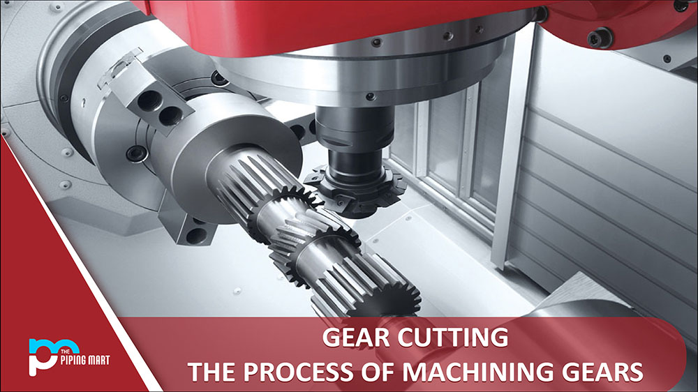
What is Gear Cutting?
Gear Cutting is known as the making or machining of gears. A spinning machine component known as a gear has cut teeth that mesh with another toothed part to transmit torque. The gear is cut from a spherical blank with teeth around the perimeter. Cutting gears is a specialized task. Gear cutting refers to any machining process used to create gears. Since toothed gears are essential parts of mechanical power transmission, it was necessary to develop complex instruments and techniques to fabricate them accurately.
Gears are made by machining, powder metallurgy, casting, stamping, and stamping. The most popular and precise method of producing gears out of all such operations is through hobbling, broaching, milling, and grinding.
Metal, plastic, and wood are used to make gears. Even though gear cutting is necessary, different metal and plastic gears may be created without cutting using die casting or injection molding. However, some also require post-production machining.
Types of Gear and Gear Cutting Processes
Types of Gears: There are five gears: spur, helical, bevel, worm (with worm wheel), and rake and pinion. Different gear types are employed for various tasks, and these gear types typically distinguish themselves depending on their power transfer model.
Spur Gear: This particular type of gear has several advantages, such as being efficient and straightforward to put together, easy to align straight teeth, and little power loss due to slippage. Some disadvantages include that it must be used in parallel, is noisy at high speeds, and is not as powerful as other gears.
It may be clear why spur gear applications are advantageous. Time will be saved, and downtime will be kept to a minimum because of the efficiency and simplicity of assembly. However, it has some disadvantages, such as the noise produced at high speeds by backlash and the sudden force the gear teeth receive when they first engage. Over time, the pressure may cause the gears to degrade in efficiency due to wear and tear. Plastic spur gears, which are beneficial in lightweight applications and applications where noise must be kept to a minimum, are one potential answer to this issue. A bonded plastic spur gear with a carbon steel core and MC Nylon teeth aids in reducing noise levels, much as the plastic spur gear.
Due to their straight tooth shape and placement of the bore, spur gears can only engage correctly if they are utilized in parallel.
Anyone can synchronize the rotational direction of two opposing gears using the Bearing Built-In gear type. The keyless spur gear is another unique kind of gear. Three types of keyless spur gears exist E, F, and G.
- E Type: With a bushing attached to the outside, the E Type keyless spur gear resembles the A Type gear in design.
- F Type: A bushing is attached to the inside of the gear’s width on the F Type gear, which has the same shape as an A Type gear.
- G Type: A bushing is attached to the outside of the keyless spur gear, comparable to our B Type gear.
Helical Gear: Helical Gear’s diagonal tooth design enables them to be quieter and smoother than spur gears because the teeth engage more gradually than spur gears. Helical gears can be positioned either parallel or across. One must choose Same Handed Gears, Both the Right ones or Both the Left, when the gears are crossed. Due to tooth slippage, helical gears are less efficient than spur gears, which is one of their drawbacks. The diagonal profile of the teeth brings on the slippage and axial thrust on the shaft. They are selecting a bearing that can withstand the axial thrust produced by the gears.
Bevel Gears: Because of their design, bevel gears can operate at a variable operating angle and are utilized for intersecting shafts. Due to their variable operating angle, bevel gears have several drawbacks, including being challenging to assemble. Similar to helical gears, it is critical to ensure the bearing can sustain the force applied to the shafts. Bevel Gears come in two varieties: Straight Type and Spiral Type, based on the manufacturer.
Straight Type: These gears are comparable to spur gears and are prone to backlash and loud noises. Due to the identical tooth orientations of spiral and helical gears, the spiral type is quieter than the latter but is more prone to tooth slippage.
Rack and Worm Gear: A different kind of gear is a rack, which comes in two designs: a flat tire and a round style. When used with a spur gear or pinion, rack gears can convert rotational motion into linear motion. They cannot operate continually because the rack will eventually run out, which is a drawback.
Flat rack gears have many mounting hole orientation options, which is helpful. Anyone can utilize side counter bored holes, bottom-tapped holes, or side-tapped holes, depending on how they intend to attach them.
Worm gears are made up of a worm gear and a worm wheel. Although self-locking and silent, worm gears have a substantial power loss and a high thrust load on the worm. Spiral bevel gears should always be purchased in pairs since only gears from the same manufacturer are guaranteed to mesh with them.
Types of Gear Cutting Processes:
Gear Broaching- The most popular technique for creating gears involves cutting off forms and is called broaching. When one passes a broach-cutting tool through an object, this usually happens. The tooth size gradually rises as the broach is moved across the thing to trim the gear to the required size.
Making internal gears and splines using broaching is suitable. A specific broaching tool should be utilized for each section to get the desired results. Making gears with rotary broaching can be possible on any CNC lathe, milling machine, machining center, or another turning machine.
Gear Hobbing- Manufacturing gear uses a rapid and practical procedure called hobbling. For high or low-volume production of external cylindrical gears, the industry frequently uses the continuous gear creation technique known as hobbing. One of the leading manufacturing techniques used in the sector is gear hobbing. The requirements for additional gearing of old and new varieties with a better and higher degree of accuracy are continuously rising in modern engineering practice. This method works well for medium to high production because of its quickness, although it is perfect for massive production.
Typically, a gear blank and hob are continually spun on a CNC gear hobbing machine to create all the gear teeth in the blank. The following gear hobbing techniques stand out: straight, helical, bevel, face, crown, and chamfering. It is the most accurate and precise procedure for making gears.
It is frequently employed to make worms, helical gears, spur gears, and worm wheels. It can also be used to create internal gears; however, the machine must be able to fit a particular head for this purpose.
How is the Gear hobbing Machine constructed?
Hob- With a rotating cutter known as a hob, the gear blank is rolled. It is a spiral cutting tool used by a gear hobbing machine to carve teeth into blanks. A gear hob, a multipoint cutting tool, is used for it. It resembles a worm gear with several straight flutes running parallel to its axis all around its circumference. These flutes are fashioned in such a way by being given the correct angles that serve as cutting edges.
In the gear hobbing procedure, the hob is fed to the gear blank while rotating at an appropriate rpm. The gear blank is maintained as turning as well. The gear blank and gear hob’s rpm are synced such that for every gear bob revolution, the gear blank rotates by a distance equivalent to one pitch of the gear that needs to be cut.
Both the hob and the gear blank move consistently and steadily. The hob teeth have a distinct helix angle and act like screw threads. It is tilted at a helix angle for the hob’s cutting blades to stay square with the gear blank during operation. A wide range of gears, including spur gears, helical gears, hearing-bone gears, splines, and gear sprockets, are made by equipment hobbing.
How does Gear Hobbing work?
It is a method in which a gear is cut using a revolving cutter called a hob and equipment blank simultaneously, with a fixed gearing ratio between the two. The gear blank is fed in until it reaches the desired depth on the revolving hob. The hob is provided across the blank’s face until all teeth are formed.
In hobbing spur gear, the hob teeth are arranged so that they are parallel to the axis of rotation of the blank. The hob’s axis is positioned over an angle for effective helix creation for helical teeth bobbing. Worm gears can be made by adequately angling the hob’s axis concerning the gear blank. Typically, the hobbing procedure involves two techniques. Traditional hobbling and climb hobbling.
Comparing the production rate to other gear-making techniques, it is relatively high. The method can make spur, helical, worm, sprocket, and spline gears among different gears. However, the rotary cutter prevents cutting up to the shoulder.
Types of Hobbing Processes
According to the hob’s feeding directions for cutting gears, the gear hobbing operation is divided into many categories. The description of the classification is provided below.
Hobbing with Axial Feed: In this procedure, the gear hob is fed against the gear blank parallel to its axis and along the blank’s face. Gears like a spur and helical gears are made using this.
Hobbing with Radial Feed: With this technique, the axes of the hob and gear blanks are arranged to parallel. In a radial direction or perpendicular to the axis of the gear blank, the rotating hob is fed against the gear blank. The worm wheels are created using this process.
Hobbing with Tangential Feed: The worm wheel’s teeth are cut using this. In this instance, the hob is held horizontally with its axis angled at the axis of the blank. The hob is positioned at the whole depth of the tooth and fed axially forward. To the face of the gear blank, the hob is provided tangentially.
Milling gear cutting- In this procedure, a form cutter on a milling machine is used to cut the gears. This cutter moves axially to create gear teeth with the exact length and depth. After missing a tooth, the edge is removed to allow the gear blank to rotate to the following position. The form cutter begins cutting the next tooth when the blank is turned again until all teeth have been carved out.
Since this process usually takes a long time, its manufacturing value is diminished. This method is used when making a small number of gears with a low requirement for precision.
Gear Grinding- Grinding gears is a different method of gear production. The surface material on the gear blank is removed through friction during gear grinding. This is accomplished by rapidly rubbing a rough surface on a piece of metal to remove unnecessary material from the gear.
Small fragments are removed one at a time throughout this procedure without harming the remaining material. Depending on the technology being used, properly fabricating the gear teeth from the gear blank is necessary for gear grinding. The two fundamental technologies of form grinding and producing grinding make up the gear grinding frequently utilized in industry.
Gear Shaping- This is the earliest way of producing gears, in which putting a gear blank in the shaper serves as the means of gear cutting. In this technique, the cutting tool is fashioned into the contour of a tooth. The gear shaper machine’s pinion-shaped cutter is the other. It is applied when cutting a gear blank with an edge that resembles a gear.
The cutter’s and the blank’s axes of rotation ought to be parallel to one another. Both low and high production levels can use this technology. The gear shaping process is mainly used in gear cutting to create clutch teeth, splines, and other low-quality gears.
Templet Gear cutting- A single-point cutting tool is used in this technique to create a gear tooth profile, which is then produced by a device that is reciprocated and made to follow a guide route by a temple whose profile matches the form of the gear tooth bring the cut. Following the completion of one tooth, the blank is indexed as usual. The temple method creates massive spur gear teeth and accurately cuts bevel gears.
Gear Finishing- The technique of completing a gear using a robust rolling die and an extremely accurate tooth profile is known as gear finishing. The gear that needs to be finished is sandwiched between two dice, and all three are turned on their axes. Both rolling dies are now applying pressure to the gear that needs to be finished. Their interaction surfaces are smooth throughout this process, improving their performance over time. High-speed operating is efficient and noiseless. The classic methods for polishing gears include grinding, lapping, honing, shaving, and burning.
Advantages and Disadvantages of Gear Cutting Processes:
Gear Broaching
Advantages:
- More quickly than any other metal cutting method is broaching.
- Both internal and external gear-cutting operations can be carried out with the broach.
- This method makes it simple to obtain tight tolerances, a high degree of dimensional precision, and an appreciable surface quality.
Disadvantages:
- Equipment that is specially made has a very high starting cost.
- It is only cost-effective for mass production runs.
Gear Hobbing
Advantages:
- Because gear hobbing is a quick and continuous process, it is recognized as being more cost-effective than other gear generation procedures.
- It has shorter manufacturing cycles or a higher output rate. Gear hobbing is relatively quick compared to other gear manufacturing procedures. Because of the machine’s simplicity, it doesn’t require as much operational attention, and many units of some gears can be easily stacked to hob them simultaneously.
- In comparison to other gear machining procedures, the process has greater unpredictability in the following sense, it can create a wide range of gears, including worms, helical gears, spur gears, splines, and sprockets.
- The method of necessary indexing, as the name suggests, is relatively straightforward and able to produce any number of teeth while maintaining the module’s accuracy. Gear hobbing alone can produce a specific gear known as herringbone gear.
- This technique can handle many batch sizes (small to huge volumes). On the same arbor, multiple gear blanks can be machined at once.
- There are various types of hobs as well as various hobbing machines. One always has options because multiple versions cater to specialized uses. Hob is a multipoint cutting tool with several cutting teeth or edges. Because fewer cutting edges are operating at once, there is more time for the heat to be dissipated. There isn’t a heating or cutting device.
- Both hobbing machines and hobs come in a variety of varieties. Because numerous models are designed for specific needs, one always has options. A multipoint cutting tool called a hob has multiple cutting teeth or edges. There is more time for the heat to dissipate because fewer cutting edges operate simultaneously. No heating or cutting equipment is present.
- Although hobbing is usually used for spur gears, many other gears, such as cycloid gears, helical gears, worm gears, ratchets, splines, and sprockets, may also be made using this technique.
- But not just anyone can operate a hobbing machine. Hobbing may be a highly accurate procedure that produces high-quality gears.
Disadvantages:
- This process is not implemented to produce internal gears.
- It possesses restricted adjacent shoulders more significant than the gear’s root diameter.
- Serrations and splines are inappropriate for hobbing.
Milling gear cutting
Advantages:
- Gear milling can produce precise results and cuts.
- Customization and multiple simultaneous cuts are both allowed.
- The work is finished more accurately than with alternative methods.
Disadvantages:
- It might use more electricity when in use.
- Processes must be correctly carried out by skilled personnel.
Gear Grinding
Advantages:
- Ground gears have a unique gear design that offers excellent meshing effectiveness and steady operation.
- It produces more cuts and operates more silently.
- They are helpful when energy is needed since they can manage heavy loads.
Disadvantages:
- Removing the necessary amount of work requires additional time.
- The method and gadget are considered to be heavily priced.
Gear Shaping
Advantages:
- Gear shaping can quickly cut spur, helical, rack, and internal gears.
- The cutter is independent of the number of teeth on the gear since it may cut gears with various teeth using the same module.
- It is ideal for batch and medium-sized production runs.
Disadvantages:
- Only if there are enough grooves and undercuts in the job should the gear or spline be cut.
- Compared to gear hobbing, it has less stiffness.
Pipingmart is B2B portal specializes in industrial, metal and piping products. Also, share latest information and news related to products, materials and different types grades to help business dealing in this industry.