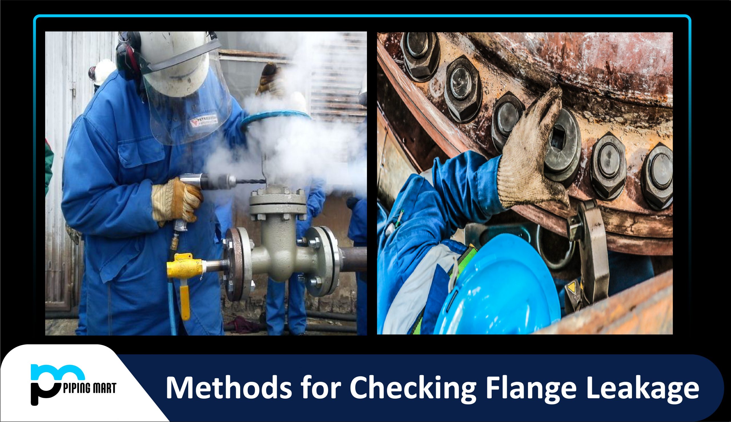
Flange leakage is a major issue in the piping industry. It has the potential to be extremely dangerous. As a result, the chances of leakage must be examined throughout the design stage to decrease the possibility of leakage during actual functioning.
- Flange leakage is primarily determined by the relative stiffness of the flange, gasket, and bolts.
- Flanges are designed to be leak-free when cold under hydrostatic test pressure and hot under operating pressure.
- The bending moment in the pipe is not considered in the flange design (ASME B 16.5). This produces a wire drawing effect on the flange’s mating surface. When a flange joint is placed near a location of significant bending moment, extra flexibility is required. As a result, leakage testing is essential.
Process Piping Flanges are manufactured in compliance with ASME Boiler and Pressure Vessel Code, Section VIII, Division 1, Appendix 2, utilizing ASME B 31.3 acceptable stress and temperature limitations.
Flange Leakage Analysis Criteria
When flange leakage testing is required, the criteria should be specified in the ITB (Invitation To Bid) documents or project specifications. However, as a general principle, the following can be used:
- Flanges with a rating of 600 or higher
- Flanges having a rating of 300 and a diameter of more than 16 inches
- Category M fluid service pipe flanges
- Pipe flanges transmitting hydrogen or another combustible fluid
- PSV lines with NPS of 4 inches or greater
- All Jacketed Piping Flanges
- Flanges with extremely high bending moments determined by the stress engineer
This is not an exhaustive list. For additional information on flange leakage criteria, always refer to your stress or project specifications.
Flange Analysis Methodology
The Process or Power Piping Industry uses 3 frequently used methods. These are examples.
- Pressure Equivalent method using the ASME B 16.5 pressure temperature table
- ASME BPVC Sec VIII Div 1 Appendix 2 method
- NC 3658.3 Method
Checking Flange Leakage Using the Pressure Equivalent Method
The axial force (F) and bending moment (M) on the flange are transformed into equivalent pressure (Pe) using the following equation.
- Equivalent Pressure for Axial force, Pe1=4F/ΠG2
- Equivalent Pressure for bending moment, Pe2=16M/ΠG3
- Here G=diameter at location of gasket load reaction =(Gasket OD+ID)/2 when bo<=6 mm =(Gasket OD-2b) when bo>6 mm. Here bo=basic gasket seating width as given in table 2-5.2 of ASME sec VIII
Add these two equivalent pressures to the pipe design pressure (Pd) to get the total pressure (Pt=Pd+Pe1+Pe2), which you can then enter into the ASME B 16.5 pressure-temperature rating table for the flange material. If Pt is less than the pressure allowed on the rating table for the related temperature, the flange will not leak.
Checking Flange Leakage Using the ASME BPVC Sec VIII Div 1 Appendix 2 Method
This method calculates flange stresses (longitudinal hub stress, radial flange stress, and tangential flange stress) using ASME code equations/formulas. These measured stresses are then compared to the allowed stresses specified in the BPVC Code Sec VIII Div 1 Appendix 2, Clause 2-8.
To calculate flange stresses, first determine the flange moment, which is affected by bolt load. The bolt load must be measured for two design conditions: operational and gasket seating, with the most severe regulating. The above-mentioned code can be used to get more information about the equations and computation methods.
Checking Flange Leakage Using the NC 3658.3 Method
The flanges are analyzed utilizing the ASME BPVC Section III Subsection NC-3658.3 technique in this method. The predicted flange moments are compared to some restricted values calculated from code equations.

Pipingmart is B2B portal specializes in industrial, metal and piping products. Also, share latest information and news related to products, materials and different types grades to help business dealing in this industry.


