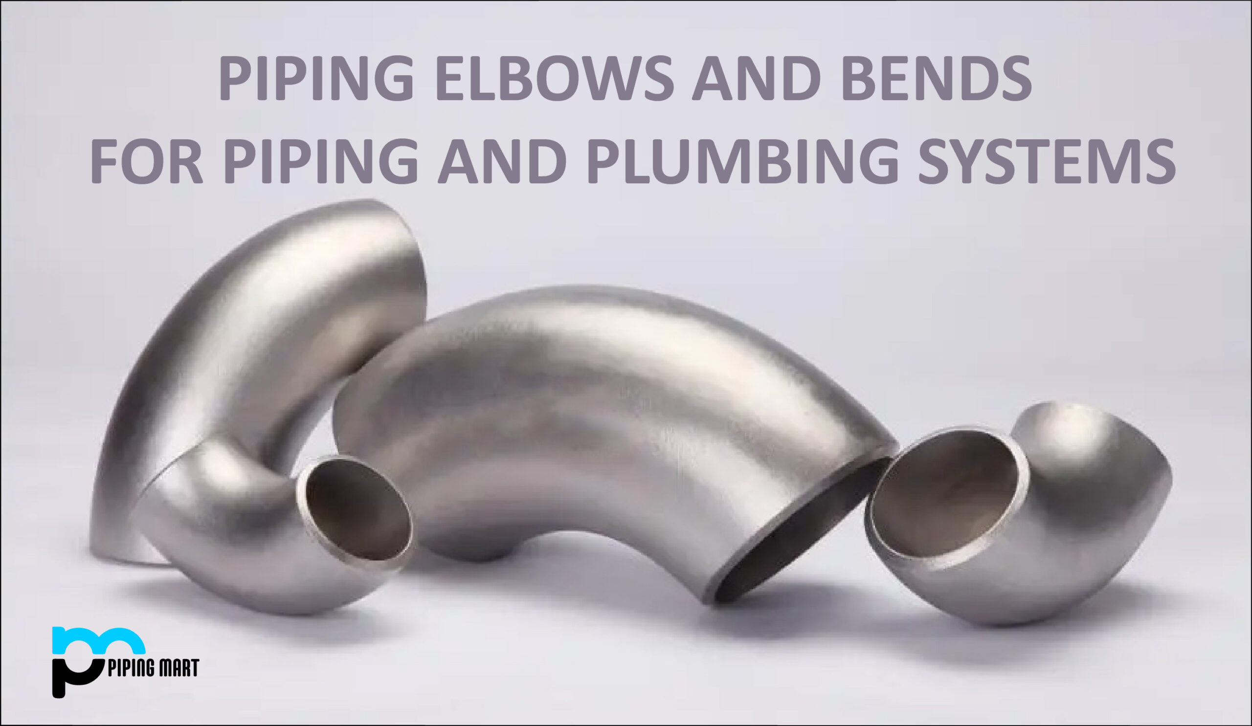
Piping Bends
Piping bends and elbows are essential pipe fittings that are regularly utilized in piping systems to change direction. Even though the terms “piping bend” and “piping elbow” are occasionally used interchangeably, they are not the same thing.
What is Piping bends?
A piping bend is merely a technical name for an “offset” in piping, which is a change in the piping’s direction. By using pipe bending, systems can still route materials through intricate piping networks while minimizing pressure changes. It indicates that there is a “bend”—a shift in the piping’s direction—but it doesn’t provide a precise engineering definition of the direction or degree of the bend. On-site bending machines (both hot and cold) are typically used to make bends tailored to a particular demand. Because fewer expensive fittings are required when using bends, it is more economical.
Pipe bends are frequently simple to install inside a processing system utilizing common welding procedures, flanges, or other connection techniques because the majority of bent pipes do not change the ends of the piping.
Additionally, due to the wide range of pipe bend sizes and materials, they can be used to transport everything from hot or caustic liquids to sustained pressure and movement in high viscosity liquids or those with suspended particulates, such as the silica sand-heavy slurry lines used in the Oil Sands.
Methods of Pipe Bending
While there are several ways to bend pipes, most of them fall into one of two groups:
- Cold bend
- Hot bend
While hot bending techniques use precise heating to limit the effort needed, cold bending techniques frequently rely on brute physical force to help the pipe take on its final shape. Each technique has special advantages that will affect the pipe’s ultimate shape and degree of bendability.
Cold bending methods are as follows:
- Compression Bending: The compression bending method uses a pushing force, as the name implies, to inflict the desired deformation on the pipe material. This is one of the most basic pipe-bending techniques and is typically employed in the production of electrical conduit pipes, which only need basic bending formations.
Common components of a compression bend include a mandrel, a clamp die, pressure die, a wiper die, and a bend die.
The main part that provides pressure to the pipe specimen to mold it is the bend die or tooling component. Similar to how the clamp die holds the specimen in place as it is being built, the wiper die guards against material flaws occurring as the process is running. Although the mandrel can be a component of a compression bending machine, you’ll learn later that it’s much more common in the mandrel tube bending method.
Both manufacturers and end users can profit from the compression bending machine’s various advantages. One benefit of the process is that it doesn’t necessitate a lot of intricate tooling components. It can also effortlessly create precise shapes and bends.
This method does have certain drawbacks, as usual. It cannot create complex forms because of its simplicity. Additionally, the lead time is excessive, which in certain situations renders it practically unworkable.
- Rotary Draw Bending: Making ensuring that the pipe’s diameter remains constant during the procedure is difficult with these tube-bending processes. This is relevant, particularly if the pipe will be utilized for tasks that need it to sustain a steady flow of fluid pressure.
The push/compression bending machine may not actually be able to make intricate bends, as was previously indicated. Additionally, there is a chance that the specimen will develop permanent abnormalities that may be challenging to repair.
The rotary draw bending machine is used in these circumstances. As the machine is supported by clamps that enable the pipe to be dragged towards a specific form that also has the same radius as the pipe, this method offers greater precision for the tubing component.
The pipe can have severe bends while still maintaining a high level of accuracy and uniformity when this is taken into account. Roll cages, railings, bicycle handlebars, and other tubular components used in pieces of machinery and structural frameworks are frequently bent using the rotational draw bending process.
- Roll Bending: The roller components that move continually through the process are the roll bending machine’s most distinctive feature. This technique is not limited to pipes; it can also be utilized with sectional sheet metals or extruded sheets.
The machine that is mostly utilized for the roll-bending process is known as the angle roll. Given its versatility, manufacturers frequently add adjustments to the equipment to make it ideal for sheet bending.
The machine’s storage capacity has various restrictions, and it might not be able to process pipes with thicker walls. It might also only apply to items made of aluminum, stainless steel, and other machinable materials.
Bike, motorcycle, and automobile rims, as well as other circular metal pieces, are some popular uses for the roll bending machine.
- Mandrel Bending: A mandrel or rod is first put into the tube as it is being created in mandrel tube bending. A flexible section that comfortably conforms to the contour is a part of the mandrel. As a result, the pipe can be continuously bent in the desired direction without being damaged by the rotary bending machine.
Its function is to support the tube, and it frequently works not only with the rotary draw bending machine but also with other machine types. Although more expensive than a standard bending machine, it does offer a faster lead time and may be used repeatedly without losing quality.
Hot bending Methods– Although there are a few minor differences among the various hot pipe bending techniques, almost all of them use induction bending.
Before applying pressure to create the desired bend, this technique precisely warms the pipe using an induction heating coil.
Without the use of filler materials, mandrils, or other modifications to prevent distortion, it can achieve bends of comparable or superior quality with far less physical effort than cold bending techniques.
Induction bending alters pipe thickness but reduces diameter reduction at the bent spot.
The extrados, or the outer area of the bend, typically becomes narrower while the inner section of the bend typically thickens.
The technique is most frequently applied to bends with long radii and big diameter pipework and tubing.
It can also be used for bends with short radii and lower pipe sizes.
Materials Used for Pipe Bending
Depending on the metals employed, many pipe-bending techniques exist.
However, a variety of ferrous and non-ferrous materials, are suitable for induction bending due to the lower force needed to attain common angles. Some materials are: Metal and steel alloy pipes, pipes made of stainless steel, metallic tubes, copper and nickel pipes
This is especially true for thinner metals, which could twist, squeeze, collapse, or exhibit other distortions when bent using cold techniques.
Pipe Bend Fittings and Sizing
Pipe bends are typically measured about the nominal pipe size or diameter (D).
For instance, long radius elbows (often denoted as >1.5D) have an end-to-center dimension that is 1.5 times the diameter.
The end-to-center measurement of short radius elbows is the same as the pipe diameter.
By dividing the D designation by the pipe’s diameter, it is possible to calculate the radius of the centerline of bent pipes and tubes.
For instance, the centerline radius of a 5D pipe with a 10-inch D will be 50 inches.
For a better understanding of the space needed and how the 180-degree pipe bends will fit, a new measurement based on the center to center dimension is used.
Similar to elbows, you can calculate the center-to-center dimension of 180-degree pipe bends by multiplying the diameter by the D suffix.
180-degree pipe bends with a small radius are 2D, whereas those with a large radius are 3D.
Accordingly, a 4-inch pipe with a short radius bend would have an 8-inch center to center dimension, whereas the identical 4-inch pipe with a long radius bend would have a 12-inch center to center size.
The tangent ends of induction-bent pipe can easily be matched to existing piping by diameter, flange, valve, or fitting needs and are frequently unaffected by the bending process, whether you’re looking at elbows or 180-degree bends.
Although measuring and fitting bent pipes may initially appear difficult, once you have a basic grasp of the proportions involved, it’s easy to match them to your current system or incorporate them into a new design.
Piping Elbows
What are Piping Elbows?
A Piping Elbow is a particular, standard, engineering bend that is pre-fabricated as a spool piece (based on ASME B 16.9) and intended to be screwed, flanged, or welded to the piping it is associated with. Either 45 or 90 degrees can be used for an elbow. Although most elbows are characterized as either “short radius” or “long radius,” bespoke elbows are also possible.
A pressure piping system’s critical component for changing the direction of fluid flow is the steel pipe elbow. It is used to join two pipes with the same nominal diameter or different nominal diameters and to turn the pipe and subsequently the fluid direction in a 45- or 90-degree direction. Because of impact, friction, and re-acceleration, this shift in fluid flow direction results in additional pressure losses for the system.
Features of Piping Elbow
In addition to the minimum size, the term elbow must always include the qualifiers of type (45 or 90 degrees) and radius (short or long). Elbows can turn in any direction and at any angle as needed. The angle by which the flow direction changes from its initial flowing direction is known as an elbow angle. Even though However, a change in direction greater than 90° at a single point is not preferred. An elbow angle can be anything greater than 0 but less than or equal to 90°. In such cases, a 45° and a 90° elbow are typically combined when laying out the piping.
Classification of Piping Elbows
Piping elbows can be categorized using several factors, including, direction angle, length and radius, connection to the pipe, and construction material.
- Elbows Based on Direction Angle
Elbows can be classified into several degrees, such as 45 degrees, 90 degrees, and 180 degrees, which are the most common elbows, based on the direction of fluid flow through the pipes. For some unique pipelines, there are also 60- and 120-degree elbows. This degree only serves to illustrate the angle at which the fluid flow will shift following passage through the specified elbow.
- Elbows Based on Length and Radius
The center line from one end to the other face, the space over which the flowing fluid changes direction, and the elbows are divided into these two groups. It is referred to as the “Center to Face” distance and corresponds to the radius of the elbow.
Elbows are divided into long radius and short radius elbows. The major difference between long and short radius elbows is their length and curvature. In comparison to a long radius elbow, a small radius elbow will be giving the piping a sharper turn. The radius of curvature is 1.5 times the nominal diameter of an elbow with a large radius. The radius of curvature in a typical elbow is one time the pipe’s nominal diameter.
In comparison to short elbows, long radius elbows offer the fluid less frictional resistance. Less pressure drop is produced by long radius elbows compared to short radius elbows. Long radius elbows are more expensive than short radius elbows.
Where there is a lack of room, short radius elbows are used.
The elbows can also be categorized as being at 45, 90, or 180 degrees, also known as a return elbow. The fluid or piping is rotated at 45 degrees by the elbow, and so on.
- Elbows based on Connection with Pipe
- Butt Welded Elbow: Steel elbows that have been hot pressed or forged are known as butt weld elbows. The steel pipe and elbow are directly welded together as the connection method. Beveled ends of butt welded elbows make welding easier. Most of the time, a bevel provides for a full penetration weld. The majority of elbows with higher pressure and temperature are butt welded.
- Socket Welded Elbow: The end of the pipe and fittings also have a socket weld elbow attached. The elbow of the socket weld has a trapezoidal end. Since the outer diameter of the pipe and the diameter of the Socket Welded elbow match, we may put the pipe end into this space and then weld the two together. The elbow diameter is less than the actual diameter of the elbow end.
- Threaded Elbow: The threaded elbow has a similar design to the Socket welded elbow, but the thread has been machined onto the inner surface of the trapezoidal section. It is simpler to install and remove, which is advantageous for pipeline maintenance and repair.
- Other Type of Piping Elbow
Other types of piping elbow which are used but not commonly include:
- Reducing Elbow: A fitting called a reducing elbow is used to connect two pipes of various sizes. The reducing elbow gets its name from the way it resembles a reducing piece and an elbow put together. The reducing elbow decreases welding by more than one-third and eliminates one pipe fitting (the reducer). Additionally, the arc of the decreasing elbow’s steady diameter reduction lowers flow resistance, lessens the impact of stream turbulence, and maybe prevents internal erosion. Large pressure drops in the line are prevented by these features. It is a non-standard item for many vendors, which results in a high price and a lengthy delivery time. If the circumstances permit, using a “regular” elbow with a separate reducer is a possibility.
- Male and Female Piping Elbows: Male and female pipe elbows are common tube fittings that change the direction of fluid flow in a piece of tubing. Fifty percent tube is connected to a female tapered pipe thread using a male pipe elbow and a male NPT thread using a female pipe elbow. These particular tube fittings, such as male and female elbows, have been created for use with the instrumentation, process, and control systems and machinery used in pulp and paper, chemical, petroleum, fluid power, and electronic industries.
Materials Used for Piping Elbow Construction
Commonly materials such as steel, carbon steel, low-temperature carbon steel, alloy steel, and duplex steel Elbows in nickel alloy are used in the making of piping elbows.
Thickness Requirements of Elbows
The inside radius of an elbow is its weakest area. Only the center-to-face measurements and a few “squareness” dimensional limits are standardized by ASME B16.9. Even though the wall thickness is not regulated throughout the rest of an elbow, it is at the weld line site. The minimal tolerance, according to the standard, must be within 12.5% of the pipe’s minimum ordered wall thickness. The fitting’s ends are the only places where a maximum tolerance is mentioned. Many manufacturers of butt weld elbows offer one schedule of larger thickness so that enough wall thickness is retained after forming.
Difference between Piping Elbows and Bends
It is essential to note that all bends are elbows, but not all bends are elbows.
- Elbows are subject to size, bend radius, and angle restrictions set by industry regulations. Typically, the angles are 45 or 90 degrees. Whereas, all additional offsets fall under the category of pipe bends.
- While elbows are prefabricated, standard, and readily accessible off the shelf, bends are typically built or fabricated according to the piping’s needs.
- Elbows possess sharp corners but piping bends on the other hand do not. The amount of material that can be thinned out safely to hold the pressure of the fluid to be contained is limited by pipe bending techniques. Elbows can be acute like right angles and return elbows that are 180 degrees because they are prefabricated, cast or butt welded. Although the bends are made to order, the elbow is a conventional fitment.
- There is less pipe friction and flow is smoother in bends since the pipe is bent without the need for welding. The welding process can cause some friction in the elbows.
- Elbows have a smaller radius than bends.
- The radius of curvature typically represents the most fundamental difference. The radius of curvature of an elbow typically ranges from one to twice the diameter of the pipe. The radius of curvature of bends is greater than double the diameter.
Pipingmart is B2B portal specializes in industrial, metal and piping products. Also, share latest information and news related to products, materials and different types grades to help business dealing in this industry.