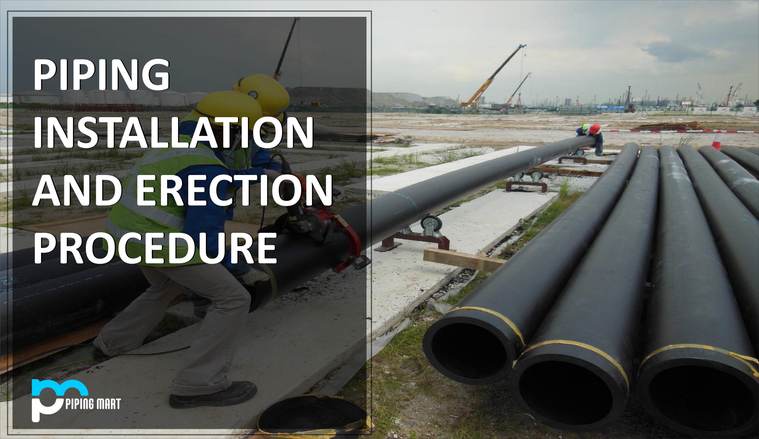
The laying of the pipe system and its associated accessories to prepare it for fluid transfer is referred to as piping installation or erection. Proper piping installation following regulations and specifications is critical to safety and operation. The next step in piping fabrication is to make pipe spools at the fabrication shop by cutting the pipes to the exact lengths and requirements. These prefabricated pipe spools are delivered to the job site or plant and installed. Pipe erection is the installation of piping spools on-site following isometric or piping general arrangement drawings. During pipe installation, the piping coordinates are matched with the designs.
Piping Installation Requirements
At the construction site, piping is installed using proper engineering work techniques and drawings. During pipe installation, the following are the primary inputs:
- Structure drawings [for the framework, beams and channels are often used].
- Piping and GA drawings
- Piping isometrics
- Drawings from the Pipe Support Standard
- P&ID
P&IDs are considered the piping’s heart because they include information such as pipeline number, size, material, and insulation.
Process and physical data, operational conditions, stream flow details, equipment numbers, and so on.
Proportionate drawings with correct dimensions are represented, as are pipe fittings, valves, flanges, special components, tables with a list of all fittings in the drawings, and so on.
The Piping GA drawings show the locations of the plant’s main equipment, main piping items, fittings and valves, nozzle orientation of the concerned equipment, and so on.
Piping Installation Technique
Piping installation typically begins after civil supports and significant equipment has been installed on the construction site. Pipe installation is divided into the following stages:
- Erection of Pipework
- Flanges for piping, valves, flange connections, and equipment installation
- Installation of Pipe Supports
- Pressure testing
- Painting and Insulation
- Identification and marking
- Installation of Expansion Joints
- Drains and vents
- Installation of Underground Pipes
Pipework Erection Procedure
Proper planning should be made to erect piping, area-wise, following piping isometric and GA drawings. The following piping erection guidelines should be followed:
- All tools, equipment, ropes, and pipes must be examined and certified in accordance with HSE specifications before erection to ensure that they are safe and ready, as well as clean and free of loose contaminants.
- Pre-fabricated spools must be easily identified and numbered/tagged.
- Pipework should be installed on supports designated for each line. Before erection, primary pipe supports can be welded using pipe support drawings. The number of temporary supports must be kept to a minimum.
- Undue stress should not be imposed to force the piping to stay in place.
- Pipe gaps should be sealed during erection to keep moisture and harmful substances out.
- Pipe installation on pipe racks should be done from a lower to a higher elevation.
- Before installing small-bore piping, large-bore piping must be installed.
- Piping joints must be positioned properly.
- Pipe clearances should be maintained between other pipes, equipment, and structures.
Installation of Piping Flanges
Pipe flanges should be brought up flush and square without being forced to bear uniform bolt stress and gasket compression. Line parts such as orifice flanges, spectacle blinds, strainers, and so on must be placed correctly. A reasonable bolt tightening sequence (hydraulic bolt tensioning & torque tensioning) must be followed.
The flange connections to this equipment must be checked for misalignment, excessive gaps, and so on. Flange covers must be kept on all flanged connections to the valve or equipment until both side flanges are ready for mating connection.
Extra care should be taken while connecting flanges to pumps, turbines, compressors, cold boxes, air coolers, and so on. Blanks or spades should be used on equipment to prevent internal pipe debris from entering. Before gasket installation, bolting must move easily via accompanying bolt-holes at a right angle to the flange faces, and a clear gap between the two flange faces must be maintained.
Assembling Pipe Support
- Use relevant pipe support details drawings when installing pipe supports.
- No additional stress should be generated to accommodate the support.
- Install the pipe shoe in the centre of the beam with no offset.
- If spring supports are required, they should be locked until hydro testing and insulation are completed. The manufacturer’s installation instructions should be followed.
- Where PTFE plates are utilized to reduce friction, sand ingress between the SS and PTFE plates should be avoided.
- Piping must be well-planned to allow for easy removal of equipment for inspection and service and must be arranged to allow for pipe-supporting.
Pressure Testing
Hydrostatic or pneumatic testing should be performed in accordance with the specifications to ensure the system’s integrity. If there is a leak, it is repaired and re-tested.
Insulation and Painting
After pressure testing, uncoated pipes are painted in accordance with the standards. The insulation method is used to insulate high-temperature lines.
Marking and Identification
All pipes and fabricated fittings are marked and numbered on the outside for simple identification of lines, services, and so on. Stamping, tagging, stencilling, or any other permanent marking method is commonly used.
Installation of Expansion Joints
For important piping systems, expansion joints are usually required. The bellows should be installed by the vendor’s instructions and installation drawings. As specified in the detailed drawings, the piping should be properly aligned with the expansion joint.
Vents and Drains
Vents and drains should ideally be located in the isometric or GA drawings. If high-point vents and low-point drains are not included in the designs, they must be installed according to the guidelines of the Engineer-in-Charge/Job Standards/Piping Specifications.
Installing Underground Pipes
- Before beginning underground pipe installation, ensure that trench excavation follows the approved drawing.
- Final measurements, tests, and surveys must be completed prior to backfilling.
- The depth of cover specified in the GA drawings must be maintained.
Pipingmart is B2B portal specializes in industrial, metal and piping products. Also, share latest information and news related to products, materials and different types grades to help business dealing in this industry.