What are Heat Exchangers?
To put it simply, a heat exchanger is a device that transfers heat from one medium to another. A hydraulic oil cooler, for instance, generally removes heat from hot oil by utilizing cold water or air. Alternatively, a swimming pool heat exchanger warms the pool water using hot water from a boiler or a solar-heated water circuit. Through the materials of the exchanger, which separate the working media, heat is transported through conduction. An air-cooled heat exchanger cools a liquid by passing cool air through a core of fins, whereas a shell and tube heat exchanger transfers fluids over and through tubes.
What is the use and functioning of a Heat Exchanger?
Heat exchangers are essential in several thermal engineering disciplines, including air conditioning, electronics cooling, refrigeration, and power system cooling. Improved heat transfer methods offer:
Increasing or decreasing the surface area (as a result of expanded or fin surfaces) without changing the thermal resistance (1/hA) of a typical design
The method that is most frequently utilized is passive augmentation.
The active improvement involves the direct injection of outside power
compound improvement using two or more techniques.
Flow regime and heat transfer mode.
Laminar or turbulent flow, single- or two-phase flow, free or forced convection
Application type comprises two-fluid HE vs. single-fluid HE.
New types of heat exchangers are constantly being developed to lower the size of the heat exchanger and improve its capabilities in terms of pressure drop or heat transfer capacity. Research in these areas also considers design techniques, numerical tools for analyzing heat exchanger performance, and the amount of time needed for such a tool to produce a workable design.
When designing aviation heat exchangers, power stress levels rise along with the need to service cooling-required energy systems. The systems of aircraft engines, lubricants, various equipment, and optional energy systems can be chilled by heat exchangers utilizing free air or other carriers during modest flight speeds. The design should satisfy both the constructional criteria for accommodating varying thermal expansions of heat exchange surfaces and the body, the compactness of the heat exchanger, and the capability of securely building heat exchangers using currently available tools. These demands frequently conflict with one another. Therefore, determining the optimality criteria in each specific scenario is crucial when developing heat exchangers.
The following are the main categories into which heat exchangers can be divided:
Recovery and regenerative processes
Processes of transfer: direct and indirect contact
Construction geometry: tubes, plates, as well as long surfaces
Mechanisms for transferring heat: single-phase and two-phase
Parallel, along with the counter and cross-flow flow arrangements
The distinction between a direct transfer of heat and an intermediary heat storage is the first. The heat from the primary medium in a regenerator is stored in a medium acting as a reservoir, and the secondary medium generates heat from that mass. A porous medium or one of the ducts through which the primary and secondary flows are directed can serve as the reservoir material.
The wall separating the two media in a recuperator allows for direct heat transfer. The second medium in a second heat exchanger can receive heat from the main method in the first heat exchanger by using an intermediate medium.
Unfortunately, the regenerator needs a temporary storage material that is an excellent heat conductor for the storage function. This significantly loses effectiveness due to the high heat conduction generated in the flow direction. However, by employing materials with poor thermal conductivity, like plastics, the only basic loss in a recuperator is the heat transfer through the wall in the flow direction, which can be minimized to less than a per mille. A recuperator can be utilized if the desired effect is attained.
Depending on the transfer method involved, heat exchangers can be categorized as either a direct-contact type or an indirect-contact type. The indirect-contact heat exchanger is the one that is used the most frequently. Heat transfer between fluids happens directly in direct-contact exchangers, ideally without mixing or leaking. Direct contact, heat exchange, and separation of the fluids occur. The main disadvantage is that they can only be used when direct contact with fluid streams is practical. These benefits include low cost and lack of fouling (absence of transfer surface).
As a result of fluid phase shifts, they are particularly beneficial in applications requiring mass transport in addition to heat transfer; this kind of exchanger rarely performs heat transfer involving solely sensible heat. Latent heat transfer accounts for a larger part of the energy transmitted in this process due to the increased enthalpy.
The choice of the flow arrangement affects the heat exchanger’s overall performance and is governed, among other things, by the available pressure drops, permitted velocities, thermal stresses, flow pathways, and necessary temperature ranges. The heat exchangers are categorized in the following diagram based on the different types of fluid stream flow available.
In the single-pass configuration, fluids enter the exchanger and make one thermal contact before leaving the component. The counter-flow design is the most effective single-pass exchanger, resulting in the biggest temperature change in each fluid. These have fluids that move in parallel but in opposite directions. The least effective single-pass device is the parallel flow when multiple fluid streams enter simultaneously. Cross-flow involves fluids flowing in opposite directions to one another and is more uncommon at extended transfer surfaces and results in two-dimensional temperature differences, which is a more unusual flow arrangement.
Using two or more passageways for each fluid, the multipass system effectively allows the fluids to pass through the heat exchanger more than once. Multipass designs are especially helpful when conditions call for long exchanger lengths or slow fluid velocities. This sort of exchanger has the added benefit of enhancing total efficiency by improving the efficiency of each pass, which increases the thermal transfer load. Reversal must occur at some point in the fluid course, as would be predicted. U-bends are generally introduced into the fluid passageways to achieve this purpose, negating the need for extra external power sources.
The added layer (in which fluid cross-flow is the general arrangement), shell, tube (often used for U-bend employment), and plate exchangers are additional classifications for the multipass layout in order of construction type.
One must maintain the heat exchangers’ cleanliness effectively and reduce fuel usage. For a comfortable flight, passenger airplanes frequently have a welcoming cabin environment. Heat exchangers are frequently employed to cool rammed air, along with auxiliary power units, gearboxes, hydraulics, and numerous other parts of an aircraft. Although temperature is the primary aspect of liquid cooling, air density and pressure are also considered when exchanger services are utilized at high altitudes.
Temperature solutions to cool aircraft fluids and electrical equipment are provided via heat exchangers, liquid-cooled chassis, and cold plates. The fan for a heat exchanger needs to be carefully chosen based on the ambient pressure to ensure adequate airflow. Because of the significantly lower air density at high altitudes, more airflow is required to remove the same amount of heat. High altitudes also have air that is substantially cooler than at sea level. Compared to air cooling, liquid cooling can perform noticeably better, behave more quietly, and is not altitude-sensitive. They also save weight and power consumption by minimizing the need for huge fans or a wide distance between components. Air filtration, avionics, and engine oil cooling systems in flight require novel compact heat exchanger (CHE) solutions.
These days, a wide range of industries are increasingly using small heat exchangers. The compact heat exchangers’ development, production, and construction materials are determined by their application. Fluids interact with a substantially bigger surface area inside compact heat exchangers, which results in faster heat transfer rates and greater efficiency. These heat exchangers are especially well suited for aerospace applications since they are lighter, more compact, and perform better thanks to increased heat transfer surfaces.
These small heat exchangers are frequently used in the aerospace industry, where size and weight considerations are made without sacrificing performance. Thin plates and fins that are piled together and typically brazed or welded also make up a small heat exchanger. The airplane heat exchangers can operate in challenging environmental conditions.
The compact heat exchanger (CHE) uses complicated flow passageways and has a small quantity and a high exchange rate between two fluid streams. The aircraft heat exchangers are subjected to difficult and demanding working conditions during operation. Therefore, it is necessary to determine the heat exchanger’s mechanical integrity and endurance life before granting flight clearance.
The performance of various types of transfer surfaces, including such offset strip fins, along with wavy fins, rectangular fins, triangular fins, and triangular and rectangular perforated fins, in terms of Colburn “j” and fanning friction “f” factors, heavily influences the thermohydraulic performances of compact heat exchangers. Previously, these data could only be produced using specialized experimental test rigs.
The analysis of small, quick, and cost-effective plate-fin heat exchangers relies on computational approaches. The following traits apply to microchannel heat exchangers used in aeronautical applications:
High-performing microchannel HEs depends on the geometry and shape of the flow channel.
To address present issues, additive manufacturing or advancements in traditional fabrication techniques are required.
Compound augmentation techniques can be used to gain more benefits.
Design of Heat Exchangers:
Rating and sizing issues are the most prevalent ones in heat exchanger design. The kind of heat exchanger architecture, flow configuration, surface or core geometry, and components must be chosen based on the problem’s parameters. The heat transfer surface area and the flow passage dimensions are available because the rating problem is concerned with figuring out the heat transfer rate and the fluid outlet temperatures for defined fluid flow rates, along with inlet temperatures and allowable pressure drop for an existing heat exchanger.
The sizing problem, on the other hand, entails determining the heat exchanger’s dimensions, that is, choosing the right type of heat exchanger and figuring out how big it needs to be to meet the demands of predefined hot and cold fluid inlet as well as outlet temperatures, flow rates, and pressure drops. The process of problem formulation and design involves the selection of the following parameters:
- Quantity, components, and flow of the configuration of heat exchangers
- Size and surface geometry characteristics
- Operating circumstances
- Thermophysical characteristics of materials and fluids
- Pressure drop and heat transfer are the primary design parameters.
- Complementary design parameters: thermal stresses and vibrations
- A compromise approach is being evaluated using engineering and economic factors.
Manufacturers frequently include a heat exchanger’s characteristic curves in their catalogs to allow for an early decision on the best option. However, this is insufficient, so the designer must conduct a thorough analysis utilizing iterative techniques that involve numerous numerical simulations or graphical evaluations.
Types of Heat Exchangers Available:
There are generally 3 types of Heat Exchangers available:
-
Shell and Tube:
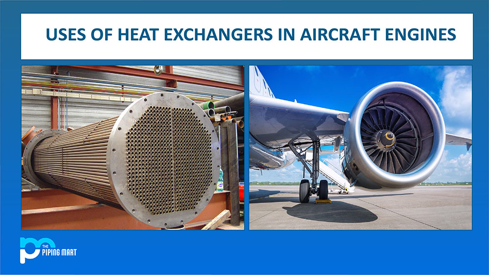
Many tiny tubes are arranged inside a cylindrical shell to form a shell and tube, heat exchanger. The tubes are placed into the cylinder using a tube bundle, also known as a “tube stack,” which can either have fixed tube plates (which are indefinitely fixed to the body) or, in the case of some other Heat Exchangers, a floating tube stack. The floating tube stack allows the tube bundle to contract and expand with varying heat conditions and to be easily removed for servicing and maintenance.
-
Plate Type:
Plate Heat Exchangers use a sequence of piled plates rather than tubes to conduct heat in a manner very similar to that of a shell and tube heat exchanger. Depending on the purpose and fluids being utilized, plate heat exchangers are often brazed or gasketed. They are the perfect option for use with refrigerants or in the processing of food and beverages due to their small stainless steel construction.
-
Air Cooled:
When a permanent cool water source is unavailable, air-cooled heat exchangers are frequently utilized in cars or other transportable applications. A fan or airflow brought about by the vehicle’s movement provides cool air. Combination cooling packs, also known as combi-coolers, are created and sold by Thermex. They integrate an engine jacket water cooler, an oil cooler, and a charge air cooler into a single device to save space and increase efficiency.
How make heat exchangers be more effective?
There are various ways to quantify heat exchanger efficiency. However, when it comes to thermal performance, there are a few important things to keep in mind:
Temperature differential:
The contrast between the hot fluid and coolant is crucial for building a heat exchanger and temperature cross-over. Keep the cool fluid at a constant lower temperature than the heated fluid. When the coolant temperature is less than when it is greater, more heat will be evacuated from the hot fluid. The same reasoning applies to heat exchangers: for example, it would be considerably more effective to use ice instead of cool water to cool down a glass of drinking water at a normal temperature.
Significant aspects are the fluid flow rates on the heat exchanger’s primary and secondary sides. The ability of the exchanger to transmit heat will grow with a larger flow rate, but this will also result in a higher mass, which may make it more difficult to transfer energy while raising velocity and pressure loss.
Installation:
The manufacturer’s instructions should always be followed when installing a heat exchanger. The best approach to installing a heat exchanger is with the fluids running in a counter-current configuration, so if the coolant moves from left to right, the hot fluid moves right to left. The coolant should enter at the lower inlet position for shell and tube heat exchangers to guarantee that the heat exchanger is always full of water. When installing a cooler for air-cooled heat exchangers, it’s crucial to consider the airflow because any obstructed core area would reduce cooling capacity. Please read our blog post titled “Why counter-flow heat exchangers are more efficient” to learn more about counter-flow and why it is more effective.
How are Heat Exchangers useful in Aircraft engines?
Heat exchangers are frequently utilized in aircraft engines and play a crucial function in indicating landscape technology. They are essential, and in which fossil fuel power generation is planned to continue indefinitely. This contains an air conditioning system and is important for the production of fossil fuels. Of course, this uses an ideal method to grab heat exchangers on a large scale and keeps updating in aviation engines. It is appropriate for purchasing the most innovative and lightweight aircraft engine equipment. This is required to obtain heat transfer performance based on the engine zone. It increases everyone’s focus on the key elements of the class of flow systems that are constantly present in fluid flow.
Look into Reducing Resistance:
Heat exchangers are a key instrument for thermal engineering sectors to use and access with the best option. This can be improved with heat transfer methods based on decreased thermal resistance. As a result, it is being updated with power system cooling effects to achieve passive improvements for decreased resistance. It is being developed to produce ever-improving performances with new types of heat exchangers. It comprises design methods and heat transfer capabilities.
Additionally, it provides numerical tools to examine how a heat exchanger performs when pressure decreases. It incorporates an optimization mechanism that considers aviation heat exchangers when the power level rises. Due to the choice of flow arrangement, it is possible to classify when taking into account the different forms of fluid stream flow that are available.
Keeping in a backup medium:
The design is almost thought to satisfy such constructional standards for the optional energy systems. These standards are implemented with heat exchange surface requirements frequently in conflict. Different roles in accessing thermal extensions are being compensated. It comprises specific cases, and heat exchangers must meet the fundamental requirements. It is crucial to access potential exchangers using optimality criteria when using them. This applies to materials regenerating from the media used to play them.
It is considered that a recuperator can function with medium-to-high intermediate values. This performs a storage function and can exchange with a heat conductor. Working toward the significant loss of heat, this effectively generates heat conduction levels. Additionally, doing so is essential for storing the primary medium with the secondary medium.
Selection Of Flow Arrangements:
For materials with low thermal conductivity, such as plastics, in a recuperator, just fundamental loss is appropriate. Utilizing the direction of flow is simple to do. For accessing a significant loss of effectiveness with conduction flow direction, this is crucial. It is characterized by low cost, absence of situational fouling, delivery between fluids, and direct contact. To employ inexpensive heat exchangers in airplanes, it must go through with the most popular type. Aircraft engines are separated utilizing any sort of indirect contact. With higher enthalpy, it is obtained with the fluid phase and optimized. In the course of this process, some energy is transmitted. Due to concerns with intermediate storage or direct heat transmission, heat exchangers are frequently employed in aircraft engines.

Pipingmart is B2B portal specializes in industrial, metal and piping products. Also, share latest information and news related to products, materials and different types grades to help business dealing in this industry.


