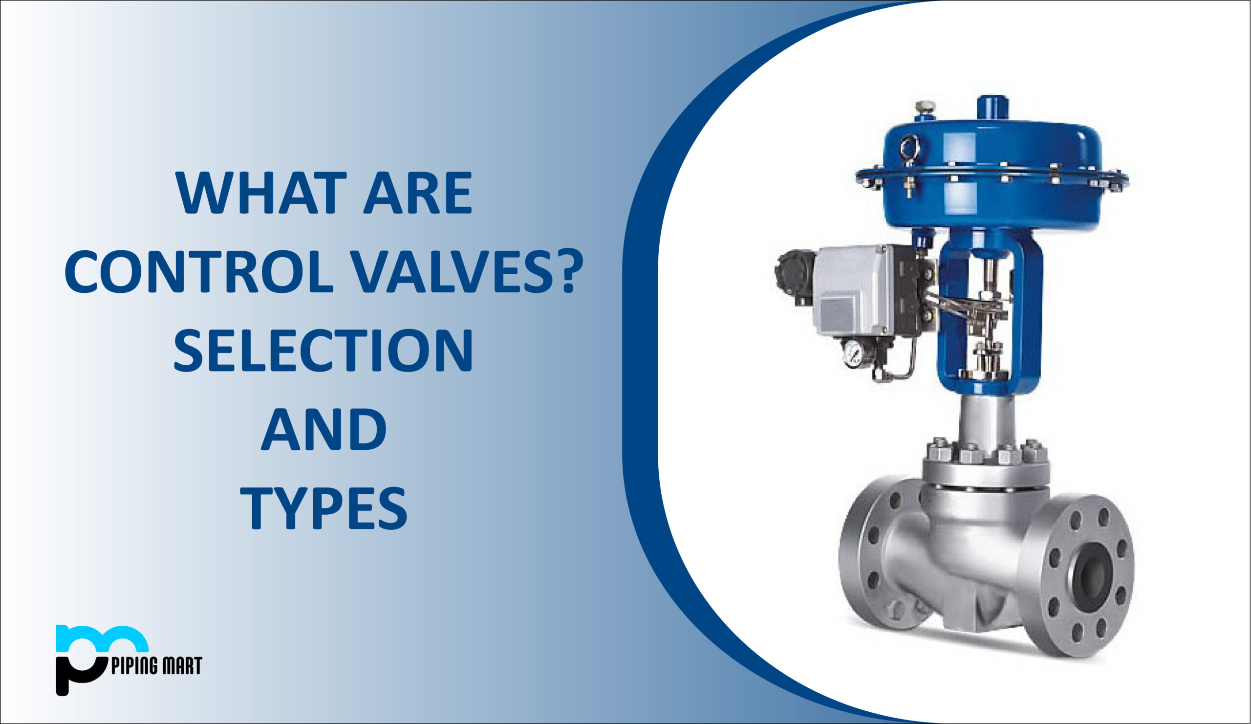
What are Control Valves?
Control valves are devices that adjust the size of the flow path to manage and regulate fluid flow, pressure, temperature, or liquid level. Control valves are widely used to control or operate any process parameters in production wells, oil and gas facilities, chemical and petrochemical industries, refineries, and power plants.
Any commodity moving via a piping system can be controlled and monitored by the control valve, an automated valve that can make exact modifications. Using an actuator and a positioner, a control valve’s job is to offer throttling control in response to signals from a control system. They are regarded as the “last control element” of a “control loop” that is automated and typically highly sophisticated.
To manage the regulation of the fluid parameter, a control valve processes the data it receives from numerous sensors and transmitters in a control loop. The control loop for a common control valve is depicted in the accompanying diagram.
Any piping system that transports liquids, gases, vapors, slurries, or mixes of liquid and gaseous phases of different flow media must include valves. While some valves are manually operated, some are powered by electric motors, pneumatic or hydraulic actuators, or a combination of these, while others are self-actuated. Metals and non-metals are used in the production of valves.
Features of Control Valve:
The globe valve is the type of control valve that is used the most frequently. The globe valve offers the most efficient approach to regulating and controlling flow, even though many different body shapes are utilized, including angle valves, three-way valves, eccentric rotary plug valves, semispherical ball valves, ball valves, butterfly valves, etc.
Control valves automatically modify the commodity inside the pipe by using signals obtained from equipment placed throughout the piping system. Although control valves are capable of numerous tasks, they are commonly employed to regulate the flow or pressure of a substance inside a pipe.
For control valves to be conveniently operated, they must be placed in a run of the pipe. Control valve manifolds are set up to accomplish this. Control valve manifolds give plant employees easy access to control valves.
Components of Control Valve:
The valve body and control valve actuator are the two most important parts of a control valve.
Body:
The media is contained within the control valve’s body as it passes through the system. The body has a valve-type control element as well as flow inlets and outputs. The valve body houses the closure element, which necessitates that it be able to transmit actuator thrust, resist media effects, and have the proper ends to assure connection to the system and avoid leaks. There are three different body kinds, and each has a different number of ports.
Single Port- The most popular control valve design is single port valve bodies. The design is available in a variety of constructions, including globe, angle, bar stock, forged, and split. They are typically employed in circumstances where there are strict shut-off requirements and can be configured for a wide range of applications. The majority of service requirements can be addressed by metal-to-metal sitting surfaces. Nitril or other elastomeric materials used to form the seal allow for this “soft-seating” to occur. The fluid pressure loads the entire area of the port when it is utilized in high-pressure applications. When choosing an actuator for the system, it’s crucial to take the unbalanced force created into account; the actuator should help regulate the media to achieve laminar flow. Single port valve bodies are typically compact and hold the seat ring using cage-style construction.
Double port- Throttling valve bodies with double ports limit the flow of fluid via them. They can be positioned easily to control the flow, making them useful as a throttling valve. Double-port systems are most effective when a large capacity needs to be passed through a large valve and can be utilized for liquid media of different temperatures.
Three/Triple Port- Three-port valves can be used to combine or reroute the flow of liquid. They keep the distribution system in balance. Piston valves, globe plug valves, and rotating shoe-type valves are all examples of three-port valves.
Control valve bodies can be altered to suit particular needs.
Actuators:
Manual Actuator- A hand-wheel or crank is used by manual/hand-operated actuators to open or close the valve. They don’t operate automatically but provide the user the option to place the valve however they see fit. In remote systems that might not have access to electricity, manual actuators are utilized; nevertheless, they are impractical for applications involving big valves.
Pneumatic Actuator- Automatic or semi-automatic pneumatic operated valves are available. They work by converting an air signal into valve stem motion by applying air pressure to a piston or diaphragm attached to the stem. For placement and use in throttle valves, pneumatic actuators are quick-acting. They perform in a straightforward, reliable manner. Because of its integrated positioner capability and high stem force output, they can be employed in challenging situations.
Hydraulic Actuator- The valve can be positioned automatically or semi-automatically using hydraulic actuators. They are used for valves that need to be opened with a lot of effort, like main steam valves. The spring force keeps the valve closed when there is no fluid pressure. When fluid enters the chamber, the pressure changes. The piston rises and the valve opens when the hydraulic fluid’s force is greater than the spring force. Hydraulic fluid, such as water or oil, is delivered to either side of the piston to close the valve while the other side is drained or bled. Hydraulic actuators come in a variety of sizes and are affordable to use with both a single valve and a valve system.
Electric Actuator- The valve can be operated manually, partially automatically, or automatically thanks to electric motor actuators. The high-speed motor is typically utilized for open and close operations and is reversible. The actuator can be controlled by the valve’s position or the motor’s torque. To automatically stop the motor at fully open and fully closed positions, a limit switch can be added. Although more expensive, electric and electro-hydraulic actuators can be utilized in situations where there is no air supply, where low temperatures could cause condensed water in pneumatic supply lines to freeze, or where extremely high stem forces are required.
Types of Control Valves:
Based on Action:
Control valves that are activated by pneumatic actuators come in two varieties:
- air to open
- air to close
They are built such that, depending on the process’s safety requirements, the control valve will either be fully open or fully closed if the air supply fails.
In the event of an air failure, the valve should be shut off if it is utilized to regulate the flow of fuel or steam. In contrast, the flow rate should be at its maximum in an emergency if the valve is handling cooling water for a reactor.
According to the schematics of these two acts, Valve A is configured to close by air, meaning the valve will be fully open if the air supply fails. The situation with valve B is the opposite.
Number of Plugs:
Control valves can also be classified according to the number of plugs they contain, like
Single-seated and double-seated valves are examples.
A single seated valve differs from a double seated valve in that it only has one plug, indicating that it is a single seated valve.
The benefit of this kind of valve is that it can be completely closed, allowing for flow variations between 0 and 100%. However, a closer study of its design reveals that a significant upward force exists in the orifice area as a result of the pressure drop across it, and as a result, a significant force is needed to move the valve against this upward thrust.
This sort of valve is, therefore, better suited for low flow rates. In contrast, a double-seated valve has two plugs; flow occurs in one orifice region and downward in the other. There is essentially little upward or downward thrust as a result. As a result, a double-seated valve requires considerably less force to move. However, the double-seated valve has one drawback. Due to the differential temperature expansion of the valve seat and stem, the flow cannot be entirely stopped. Unless both plugs are completely closed, there will typically be a tiny space between one plug and its seat. Therefore, single-seated valves are advised when the valves must be entirely shut off. However, there are numerous procedures in which it is not anticipated that the valve will function close to shutoff. Double-seated valves are advised for this problem.
Movement of Controlling element:
The mechanical motion of a control valve or any other form of the valve can be used to categorize it. The two most prevalent types of stem motion are linear and rotational.
Linear Control Valves:
The most popular kind of valve on the market right now is the linear-style valve. It is renowned for its straightforward design and convenience of upkeep. The sliding-stem design of linear valves, commonly referred to as multi-turn valves, forces a closure element into an open or closed position. These valves provide a wide range of trim sizes and design options, making them incredibly adaptable. A rotary valve is more susceptible to cavitation than a linear-motion valve. While often more expensive, linear valves provide perfect accuracy and 1:1 linear flow control.
Globe valves are linear valves with circular bodies.
Rotary Valves:
Over time, rotary valves, also known as quarter-turn valves, have changed and grown in popularity. To stop the flow, they employ a closure mechanism that spins, often through a quarter- or 90-degree range. Typically, a linear valve of equivalent size and weight weighs more than a rotary-motion valve. Additionally, rotary valve stem packing makes it simpler to regulate emissions without the need for bellows seals. They are less likely to clog in filthy service applications.
Butterfly valves are fast-opening valves made of a metal disc or vane with pivot axes that are perpendicular to the direction of the pipe’s flow. The disc seals against seats in the valve body when it is spun on a shaft. They are typically employed as flow control throttling valves.
Ball valves offer precise control and shut-off. Due to the regulating element’s design, they have high rangeability without the side load issues that plague butterfly or globe valves.
One of the most popular valves for both on/off and throttling services continues to be the plug control valve, often known as a cock or stop-cock valve. Plug valves combine a number of the best features of ball, butterfly, and globe valves. An offset plug that swings into a seat on the valve closes it. It is a rotational motion valve, which requires less actuator power and provides tight shut-off and little breakout torque.
High-Pressure Control Valves:
The High-Pressure Control Valves are a flexible answer to the needs for oil and gas production. It can be utilized in applications involving plunger lift or flow back, as a dump valve, pressure regulator, suction controller, recirculation valve, and more.
Depending on how it is configured, it uses a pneumatic input signal to open or close the valve. It can be coupled with an optional electric actuator or run on compressed air for zero-emission needs.
Selection of Control Valves:
The selection of control valves depends upon the service conditions required and load characteristics.
Controlling the Valve– A sensor element, a controller, and the ultimate control element the valve and its actuator make up a control loop. A signal from the sensing component is sent to either a single controller or a distributed control system.
The controller sends a signal to the control valve after comparing the signal to the setpoint and making any necessary adjustments. The sensing element measures and validates the correction, closing the loop.
An electronic signal is converted to a pneumatic signal by the I/P transducer. Any change in the signal should cause a control valve to respond immediately.
To function properly a valve should:
-Possess the ability to function across a broad range of fluxes;
-Precise across its operational range in response to any signal;
-Display negligible hysteresis or dead time;
-Respond to the controller’s gradual modifications (resolution); and
-Respond with the desired promptness (stroking speed).
-Some applications might not benefit from a quick answer.
Design Parameters- The fluid’s state (vapor, liquid, or two-phase), vapor pressure, flowrate, inlet, and outlet pressures, inlet temperature, density, molecular weight, viscosity, specific heat ratio, critical temperature, and critical pressure are all necessary considerations when choosing a control valve.
An adequate design margin (usually 10%) should be included in the maximum flow rate that is specified. The geometry, size, pipe schedule number, construction materials, fail-safe position, maximum shut-off pressure, and percent flash (for flashing fluids through the valve) of the system must all be known to properly specify it.
Since a control valve is power-operated, the selector must consider its response to the loss of signal or power i.e., the valve’s fail-safe mode. The failure mode of control valves is required to be closed in around 80% of applications. The valve should occasionally either drift, lock, or fail open (fail-in lock position) (slowly, to either close or open).
Trim- Trim describes the detachable interior valve components in contact with the flowing fluid. The packing, bonnet, bottom flange, and gaskets are among the parts that are not regarded as trim. The trim makes sure that the valve is shut off properly and maintains the link between flow capacity and valve-plug lift.
The choice of valve trim is primarily influenced by the fluid working conditions, the inherent flow characteristic for a certain trim from the manufacturer, and the impact of the inherent flow characteristic under various operating situations. These variables make it possible to anticipate the installed flow characteristic for each trim, which is the basis for choosing the trim.
Bonnet- The bonnet, which houses the actuator and the valve packing, also needs special attention. Frequently, bonnets are made to withstand a specified range of temperatures. An extension bonnet is utilized for high (like 450°F) and below-freezing temperature service. Extreme temperatures are isolated from the packing by this bonnet.
Noise- Control valves make noise as a result of aerodynamic forces, cavitation, or mechanical vibrations. Depending on the cavitation’s intensity, noise is produced. The noise will rise as the pressure drop across a valve increases. A control valve rattles when it is fully cavitating.
Selection of a type of valve-
Significant criteria to keep in mind while selecting a particular type of control valve are:
The pressure drop allotted to the control valve in a pumped circuit must be greater than 33% of the dynamic losses in the system at the rated flow or 15 psi.
The pressure drop allotted to a control valve in a centrifugal compressor’s suction or discharge line should be 5% of the absolute suction pressure or 50% of the system’s dynamic losses, whichever is higher.
The pressure drop allotted to the valve in a system where static pressure transfers liquid from one pressure vessel to another should be 10% of the lower-terminal vessel pressure or 50% of the system’s dynamic losses, whichever is higher.
Steam lines to turbines, reboilers, and process vessels should have pressure reductions in valves of 10% of the steam system’s design absolute pressure or 5 psi, whichever is higher.
Never let a control valve’s gain fall below 0.5.
Use the lower 10% and upper 20% of the valve stroke as little as possible. In the 10-80% range, controlling the valve is significantly simpler.
Control-valve bodies are typically one size smaller than the line size. Do not generalize if this results in the valve body is much smaller than the line size, which would lower the valve’s effective Cv.
Other factors that affect the choice of control valves include
-Controllable flow rate-When fully open, no obstructions or resistance to flow (turbulence lowers head pressure);
-Swift opening and shutting mechanism – in an emergency or for safety, a quick response is frequently required;
-A tight shut-off guards against leakage under high pressure.
-The capacity to permit flow in only one direction while preventing return;
-Opening at a predetermined pressure – process management to avoid equipment damage; and
-Ability to work with abrasive fluids; toughened material delays deterioration.
Control Valve Flow Characteristic-
Every control valve has a flow characteristic that explains how the flow rate and travel of the control valve relate to one another. A set quantity of flow is permitted through the valve at a specific percentage of the stroke when the valve opens due to the flow characteristic, which is a feature inherent to the design of the chosen valve. This permits reliable flow regulation through the control valve. Some Common characteristics are:
Equal percentage: When the valve for the temperature and pressure-control loops is not where the majority of the control system pressure drop occurs.
Linear: In liquid-level or flow-control applications where a relatively constant pressure drop across the valve is anticipated and where the valve accounts for the majority of the pressure drop in the control system.
Quick-opening: where an “instantaneously” huge flow is required, such as for safety or deluge systems, or frequent on/off services, such as in batch or semi-continuous processes.
Materials for Construction:
The specification of the hard body, trim, soft gasket, seal, and packing materials is part of the materials selection process. The body and trim must match the interconnecting piping’s material.
Carbon steel is the preferred material for noncorrosive applications (ASTM A216 Grade WCB, if cast; and A105 when forged). Valve housings for mildly corrosive applications are built of type CF8M (316 stainless steel). For very corrosive fluids, however, there are Teflon-lined housings and exotic alloys like Hastelloy, Monel, or titanium available. By hardfacing the valve internals with nickel or cobalt-chromium alloys, erosion may be halted. Both high- and low-temperature services (over 800°F and below freezing, respectively) must be taken into account. The packing and valve body should be made to tolerate high pressure. Graphite is used to support soft packings in high-pressure applications to prevent extrusion through narrow orifices.
Installation of Control Valves:
In a straight pipe run, control valves are often mounted horizontally, ideally away from elbows. The actuator is maintained vertically. To maintain continuous functioning throughout control valve inspection and maintenance, a bypass valve is fitted. To separate the control valve for maintenance, the piping system has been installed with upstream and downstream isolation valves and drains.
Pipingmart is B2B portal specializes in industrial, metal and piping products. Also, share latest information and news related to products, materials and different types grades to help business dealing in this industry.