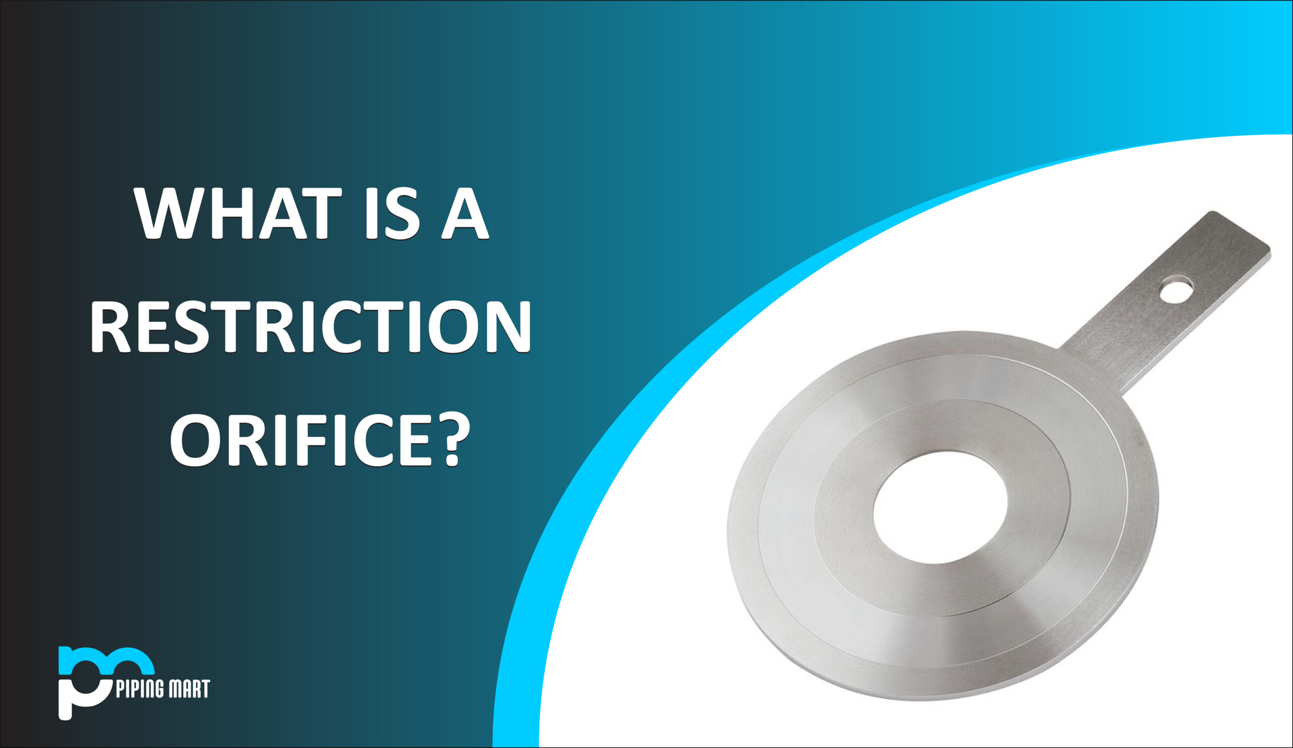
A restriction orifice, often known as a RO, is a flow control instrument device whose main purpose is to restrict the flow to obtain a controlled or restricted flow. A pressure head drop is seen from the orifice upstream to downstream due to this restriction by the orifice plate. The orifice area at the exit determines the volumetric flow rate of the fluid inside the pipe for a given temperature and pressure condition. The desired pressure drop for which the device is sized is the permanent pressure loss caused by the device. The rate of flow of particular process fluid at the output for a given pressure and temperature is determined by the area of the orifice. The high-pressure drop at the restriction orifices might lead to the vibration that is caused by sound waves. The provider is in charge of choosing, sizing, and providing the final restriction orifice. For examination of stress and noise-related issues, a professional may need to review the design and sizing of the restriction orifice.
In essence, an orifice plate is a thin plate having a hole in the center. The plate is put into a pipe’s two flanges to provide restriction or measure flow.
Types of Restriction Orifice:
Based on the desired pressure drop and flow rate, the RO should be chosen. The several kinds of RO are described below.
- Single Stage RO Plate:
A single-stage restriction orifice typically resembles square-edged orifice plates in appearance. Normally, the restriction orifice plates shouldn’t have the 45-degree bevel proving on the measurement orifice plate. However, the ISO 5167 standard is commonly used by many manufacturers to size the restriction orifice plate. The bevel and surface finish should be used to maintain the uncertainty of the downstream pressure since the discharge coefficient values and permanent pressure loss are taken into consideration from the standard.
Otherwise, the orifice’s downstream border will alter the flow pattern. And as a result, the downstream pressure may differ from the projected one.
- Single stage Multi-hole RO Plate:
Where cavitation is produced, a single-stage multi-hole restriction orifice plate is utilized to restrict flow while lowering pipeline pressure. Multi-bore will reduce noise production and the cavitation impact.
To reduce the noise produced by the device due to the high bore velocity that restricts incoming fluid, a single-stage multi-hole restriction orifice plate is used.
By using several holes, the flow at the intake is now divided into various streams, which lowers the noise that would otherwise be over the allowed level if a single hole device were employed.
- Multi-Stage RO Assembly:
When a single-stage orifice plate is unable to accomplish the requisite pressure reduction ratio due to its high need, multistage RO (MSRO) is utilized. As a result, a multistage device is just a collection of single-stage devices assembled on a single spool. It can be a single-hole multistage design, a multi-hole multistage design, or a combination of both, just like a single-stage device. Eccentric-type orifice plates are typically used in single-hole MSRO and are installed diametrically across from one another. The internal diameter of the pipe is the minimal distance that must exist between each stage.
- Multi Stage Multi Hole RO Assembly:
When there needs to be more control over noise and there is a higher pressure drop, multi-hole multistage restriction orifices are utilized.
- Conical Shaped RO:
Fix the issues caused by orifice cavitation such as erosion, vibration, and noise.
Eliminated cavitation-related harm, including Conical orifices, allow energy to dissipate inside of them rather than at pipe walls, preventing it from slamming into them.
- Critical Orifice Plate:
Maintaining the upstream pressure at a consistent level is utilized to restrict flow. This RO is designed to function in obstructed flow situations. In general, the RO should be thought of as having a thicker plate than typical RO plates.
Types of Orifice Plates:
- Square Edge Bore: The bore and bevel is the conventional technique for restricting the plate edge thickness for the common square edge concentric bore orifice. Plates will be beveled according to the most recent acceptable standards unless otherwise indicated.
- Quadrant Edge Bore: An orifice with a rounded inlet edge makes up the quadrant edge bore. The plate is counterbored to the appropriate edge thickness rather than beveled. The orifice-to-pipe ratio (d/D) affects the quarter circle bore’s radius. The radius is equal to the thickness at the neck. This bore is made especially for slurries, syrups, and other viscous liquids with Reynolds numbers under 100,000.
- Eccentric Bore: Eccentrically drilled orifice plates are those with eccentric rather than concentric orifices. To allow solids or slurries to pass through, the eccentric orifice’s bore is often encircled by a circle that is 98% the diameter of the pipe. Eccentric orifice plates are employed in a variety of sectors, including steel, paper, nuclear, heavy and light chemicals, and petrochemicals.
- Segmental Bore: For measurements in areas where particulates are entrained in a gas or liquid flow stream, segmentally bored orifice plates are available. A circle that is typically 98% the diameter of the pipe is inscribed around the circular part of the hole. Either the top or bottom of the pipe may host the segmental aperture. The sewage treatment, steel, petrochemical, and water conditioning industries all use these bores.
- RTJ Type Orifice Plate: An integral gasket, either an oval or an octagonal ring, is included in the RTJ type orifice plate for attachment between ring-type joint flanges. It is built using tried-and-true technology, has no moving components, and can withstand extreme temperatures and pressures. For clear liquids, gases, and low-velocity steam flows, orifice plates are advised. The thickness of the plate should be sufficient to prevent bending during operating conditions; it depends on the line size and differential pressure. If necessary, orifice plates can be produced in line with customer drawings. Orifice flanges per ANSI B16.36 can be supplied with RTJ-type orifice plates.
- Paddle type Orifice Plate: For measurement purposes, paddle orifice plates are mounted between normal ASME flanges, and for restriction applications, they are utilized with raised-face orifice flanges.
- For line sizes of 2 inches through 6 inches and ASME classifications less than 900, the plate and handle are one seamless piece on 1/8-inch thick orifice plates. The handle is welded to the plate as usual on all other plates; one-piece fabrication is an option. The handle is stamped with the flange ASME class and other standard data.
Applications of Restriction Orifice:
These restriction orifice devices are frequently used in the applications listed below to achieve controlled flow from the upstream to the downstream. Restriction orifices are frequently exposed to harsh fluid conditions brought on by significant pressure drops, cavitation, and sonic (choked) flow, as well as the related fluid conditions created by liquids flashing to gas. Consequently, these facts are also taken into consideration.
Downstream of Blowdown valves: The restriction orifice (RO) is used at the blowdown valves’ downstream end
These are utilized to guarantee a controlled flow rate in a blowdown header or piping.
The restriction orifice plate at the blowdown valve downstream makes sure that the flow is not excessive enough to overflow the flare header when the blowdown valve, which is often an FB or RB ball valve, opens to discharge the high pressure on its upstream. The pressure drop in the blowdown circuit that occurs across the restriction orifice is often very significant, ranging from 80 to 100 bar. The Joule Thompson effect will cause a drop in temperature during the blowdown event if a single-stage device or a device with not many stages is used to generate a high-pressure drop. As a result, the RO’s design must account for the low temperature.
Pump Re-circulation Line: In the recirculation line of centrifugal pumps, when a steady recirculation flow is necessary and control of the recirculation and forward flow rates is not crucial, ROs are also utilized.
Recirculation prevents cavitations and starvation from occurring in the pump.
To restrict gas blow-by: The transfer of hydrocarbon condensate from a high-pressure separator to a low-pressure separator is a typical example.
Typically, a level control valve (LCV) regulates the high-pressure separator’s level. To prevent separator overflow in the event of valve failure, the valve must fully open. A high rate of condensate and gas flow is present when the LCV is fully open. A restriction orifice downstream of the LCV regulates the gas flow to prevent the downstream relieving system from overflowing.
The heating medium flow into the re-boiler uses a similar application to lessen the impact of the heating medium valve failing in the open position.
Check Excessive flow: In the event of a rupture, ROs are utilized to control the excessive flow.
The hydraulic oil to the valve actuator is therefore depressurized in wellhead applications if the down holes valves must be closed owing to fire via the use of a fusible plug, which fuses and permits the hydraulic oil to leak through a RO at a constrained flow rate.
For liquid service, a cavitation zone is produced if the pressure in the vena contracta drops to the liquid’s vaporization pressure. A flow restriction will be created by this cavitation zone.
Controlled Pressurization: Many plant components must be carefully pressured with the incoming process fluid at the first startup of a processing plant.
This is such that the downstream segment will typically be under significantly lower pressure than the upstream section. The initial flow rate may therefore be extremely high if there is no restriction on the flow rate, which could harm the pipeline and equipment. For gradual pressurization, ROs are utilized. Designing for a gas flow that is constricted is the optimal situation for flow restriction.
The flow rate will be lower because it will be proportional to the square root of the inlet pressure rather than to the differential pressure during the constricted flow.
The restriction orifice plate is typically utilized in pipelines where a known/fixed pressure drop is required for noncritical flow limitation. Additionally, it might be, for example, after a control valve splits the necessary pressure loss into two halves. The RO should be sized up to the sonic condition or location where cavitation occurs based on the flow rate, upstream pressure, and needed pressure drop. The maximum pressure loss is restricted to the critical pressure drop where the sonic condition occurs for reducing gas pressure with the appropriate inlet flow rate. The RO should be sized to prevent cavitation for liquid service.
Some specific applications of Restriction Orifices include:
- They are positioned around centrifugal pumps in the minimum flow bypass lines.
- They are set up in applications for wellheads.
- In the case of a rupture, an orifice may be employed to control excessive flow.
- Simple static mixer N2 purge or constant gas seal applications
- In case minimal circumvention is required.
- Used in fluid injection, cooling, and flushing.
Restriction Orifice Standard:
Although there are no globally recognized norms or standards that specifically cover a restriction orifice, there are related references, some of which are given below:
- ISO 5167 (Part 1): General principles and specifications for measuring fluid flow using pressure differential devices implanted in circular conduits with full cross sections.
- ISO 5167 (Part 2): Orifice plates for measuring fluid flow using pressure differential devices installed in circular conduits with entire cross sections.
- IEC 60534-8-3: Industrial-process control valves – Part 8-3: Noise considerations – Control valve aerodynamic noise prediction technique.
- Other standards are ISA RP 3.2, API -RP 550/551, API 2531, API Manual of Petroleum Measurement, AGA Report No.3, API MPMS 14.3.2, ISO 5024, and ISO 5168.
Steps to Design Restriction Orifice:
The RO needs to be sized for a critical or pre-critical state based on the service and requirements. When sizing, the flow control RO plates take into account the critical pressure drop whereas the pressure control RO plates take into account the maximum pressure drop that is smaller than the critical pressure. The standard for sizing restriction orifices is ISO 5167.
The criteria listed below are used to create a restriction orifice or RO:
-According to the application to be used in
-Data prepared for the Orifice (by design engineer or vendor)
– Sizing of the restriction orifice
-Checking important design components including the cavitation index (Kc=0.93), the pressure drop, the minimum orifice diameter, the permissible space in the piping routing, etc.
-Completing the required fields in the P&ID and RO datasheets
Factors for sizing RO:
Pressure Drop- The amount of required pressure drop is a crucial consideration when sizing and choosing the RO model. Additionally, the pressure drop through RO determines its minimum necessary thickness.
Where Tmin is the minimal plate thickness necessary.
The beta ratio is β
Pl is the greatest pressure differential across RO.
D is the pipe ID, and y is the material’s yield strength for plates.
Flow Rate- The RO should be sized at a normal flow rate since the pressure drop changes as the flow rate fluctuate. It should be constructed for the necessary downstream flow rate for critical RO.
Sonic Flow- When sizing a RO for gas service, sonic flow is a key consideration. Sonic flow may happen and choke may happen when the necessary pressure drop is greater than the critical pressure drop. Sonic flow in a pipeline will cause noise and vibration, and because of the vibration, mechanical failure risks will rise.
The maximum pressure drop across a single-stage RO plate should be kept to a critical pressure drop to prevent this.
The velocity and density of a gas increase as it passes past a limitation. Because the mass flow per unit area depends on both density and velocity, there is a critical area where the mass flux is at its highest. Because of the sonic velocity in this region, increasing the mass flow won’t be possible by further lowering the downstream pressure. A choked or acoustic flow situation describes this.
Cavitation- In situations with the restricted liquid flow and a significant pressure decrease, cavitation usually happens. Cavitation, or the formation of vapor bubbles, occurs when the downstream pressure falls below the vaporization pressure.
The velocity and pressure change once the liquid has passed through the restriction orifice plate. This causes the vapor bubbles to collapse, and flashing may result.
The cavitation index of the RO should be kept below the RO plate’s incipient cavitation index.
The size of RO is strict for high vapor pressure liquid service to prevent cavitation and related effects. Cavitation and subsequent flashing could degrade the pipe downstream, leading to a catastrophic pipeline failure.
This might be avoided by restricting the sizing of RO to the cavitation index within the RO’s developing cavitation. The dependent variables for the cavitation index are the vapor pressure, the outlet pressure, and the incipient cavitation factor, which depends on the plate’s beta ratio.
Noise level- In RO, predicting the noise level involves two processes. Determine the sound power generated in the fluid as a result of pressure reduction, cavitation, and sonic conditions.
The sound level at a predefined place outside the piping must then be calculated after deducting the transmission loss through the pipe.
The sizing of RO is more important than the flow-measuring orifice because of the large pressure drop, and there are numerous factors to take into account.
Noise in the plant may result from RO that is not the proper size. Source control (preventing noise generation) or path control are two ways to reduce RO noise (pipe insulation, silencers, or increasing pipe schedule). Source control is the preferred approach since it is more efficient. Once created, sound practically travels through the downstream pipe without being attenuated. By causing excessive vibration, high sound levels inside piping systems can harm downstream mechanical parts and pipes.
Working Principle of Restriction Orifice
According to the Bernoulli’s principle, which stipulates that the pressure drop across the limitation orifice is directly proportional to the volumetric flow rate going through the orifice plate, both restriction orifice and orifice plate function.
As fluid moves through the plate, its velocity alters, which, according to Bernoulli’s equation, affects pressure. The volumetric flow rate is determined by measuring the difference between the pressures upstream and downstream.
How to Install Restriction Orifice?
Physically, the limitation orifice is a thin plate with a hole or holes in it. They are typically put between two flanges in pipe applications. When the piping is put together, the plate could accidentally be left out, or more likely it could be forgotten to be replaced when the piping is put back together after maintenance or cleaning. So it’s challenging to remove the orifice.
Difference between Restriction Orifice and Orifice.
- Purpose- Restriction Orifice is a pressure-reducing device called an orifice that is used to kill excessive pressure or reduce pressure. The orifice is the device used to measure flow is an orifice.
- Hole Profile- The restriction orifice’s hole has a straight profile. The orifice’s hole profile is initially straight before becoming beveled (notched) with a 45° inclination.
- Pressure Drop- Drop in high pressure is caused by a restricted orifice. In Orifice, the pressure decrease is minimal.
- The velocity of fluid- Sonic Velocity in RO to guarantee choked flow. Subsonic flow is present in the orifice.
- Acoustic Induced Vibration- Restriction Orifice can emit a lot of noise and is quite susceptible to AIV. The orifice is resistant to AIV.
Pipingmart is B2B portal specializes in industrial, metal and piping products. Also, share latest information and news related to products, materials and different types grades to help business dealing in this industry.