In our previous article on What Is Piping, we gave you a synopsis of Piping Isometric Drawings. Here, we’ll concentrate on becoming acquainted with piping isometrics. From becoming aware of an isometric piping drawing to learning how to read it correctly. You need to be aware of these four crucial concepts to comprehend any Piping isometric drawing:
- Co-ordinate System
- Piping Symbols
- Understanding of Directions
- Pythagoras Theorem (For Rolling movement of Pipe)
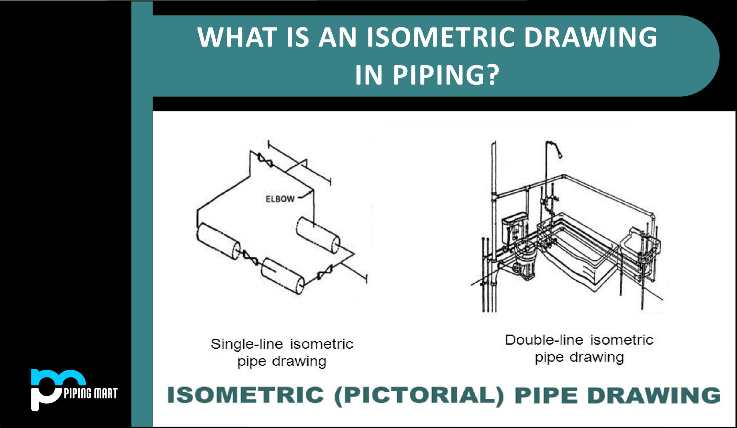
What is Piping Isometric drawing?
To execute a piping project, either in the yard for fabrication or in the field for erection and construction, piping designers must convey the same information to the person carrying out that piping work after creating a 3-D model in PDMS, SP3D, or any other program. The execution person must have access to all the necessary information. So that students can comprehend fully and develop a vision of how spools are constructed and how a pipe is connected to other pieces of machinery or unique objects.
Here, piping isometric sketching plays an essential function. This kind of drawing enables a designer to communicate with the team carrying out building projects and his ideas for piping connections. In a process plant, piping isometric represents a single pipeline with precise measurements and a Bill of Materials (BOM). It is the most significant output of any project where plumbing is essential.
Isometric drawings are, by definition, a visual depiction of a 3D routed line in a 2D plane that combines pipe height and length in a single drawing with a 30° angle on either side of the horizontal.
- The main body of an Isometric piping drawing consists of the following:
- Line Number
- Flow direction
- Piping components
- Type of solder joint and its position
- Continuation isometric number
- Coordinates and Elevation of Pipe
- Connection details with Equipment
- Section of Left or right of Piping Isometric drawing includes:
- Description of the pipe component
- Code of materials
- Size nominal of components
- The number of components
- Whether it be a field or store item
The Bottom Section of the Isometric Drawing contains the following:
- Name, Client, PMC (Project Management Consulting), and Contractor information for the project
- Information about a pipe, such as its number, size, fluid code, design, operational temperature, and pressure piping class Inch-Meter and Inch-Dia
- Created notes specifically for each drawing. e.g., Heat expansion, Stress criticality, etc.
- Calculations for Piping data from Isometric drawing
- Inch Meter = Pipe Length (in Meters) x Pipe Size (in inch)
- Inch Dia: Pipe joint size (inches) times the number of joints
- [(Pipe OD+ insulation thickness)]: Insulation Area (in m2) (each in metres) Pipe Length, x (in metre)
- Weight of Pipe: x pipe diameter (in m), x pipe length (in m), x pipe thickness (in mm), x pipe material density. CS has a density of 7.85 g/cm3.
- The following information is necessary for hydro testing: x “Pipe ID” (in meters) Length of Pipe x 2
Features of Piping Isometric Drawings
- A person can visualize a 3D view of a line by using an isometric drawing, which is a 2D representation. The following are some crucial characteristics of any piping isometric:
- All isometric drawings are created regardless of the size and length of the lines and the piping components, but this provides the precise dimensions for everything shown.
- The isometric drawing’s line diagram is unable to specify line size. The actual line size can be determined from the BOM or NB (nominal bore) remark in the isometric.
- This can also refer to a line that is not precisely moving in the directions of North, South, East, West, Up, or Down.
- This may show what kind of connections should be made between the piping elements that will be employed.
- This can provide you with information about the equipment connection, the direction of fluid flow, and a particular object related to it all on one page.
The coordinate system of Piping Isometric
I’m confident that you have studied coordinate systems as a scientific student. Yes…!! A three-axis coordinate system that is the same. X, Y, and Z axes, for example. You need only slightly modify your concept to understand coordinate systems.
When reading Piping Isometrics, you must constantly keep these three things in mind:
- While a pipeline is moving in that direction, the value of Northing or Easting always rises, and vice versa. For instance, if the Pipe went 10.94 meters southward from a position where the face of the Pipe was N 524.196, and the current coordinate of that point was 524.196-10.94=513.256. (Value of Norting after line movement).
- Only when the Line moves in an easterly or westerly direction does the value of nothing change.
- The Northing or Easting of that location remains constant whether the Line travels uphill or downwards. Only the value of Elevation will be affected.
Pipingmart is B2B portal specializes in industrial, metal and piping products. Also, share latest information and news related to products, materials and different types grades to help business dealing in this industry.