High-level noise is frequently produced while control valves are in operation. Pressure reduction is a technique for reducing noise and vibration. For this, we add some equipment, such as diffusers, that reduce noise downstream from the control valve.
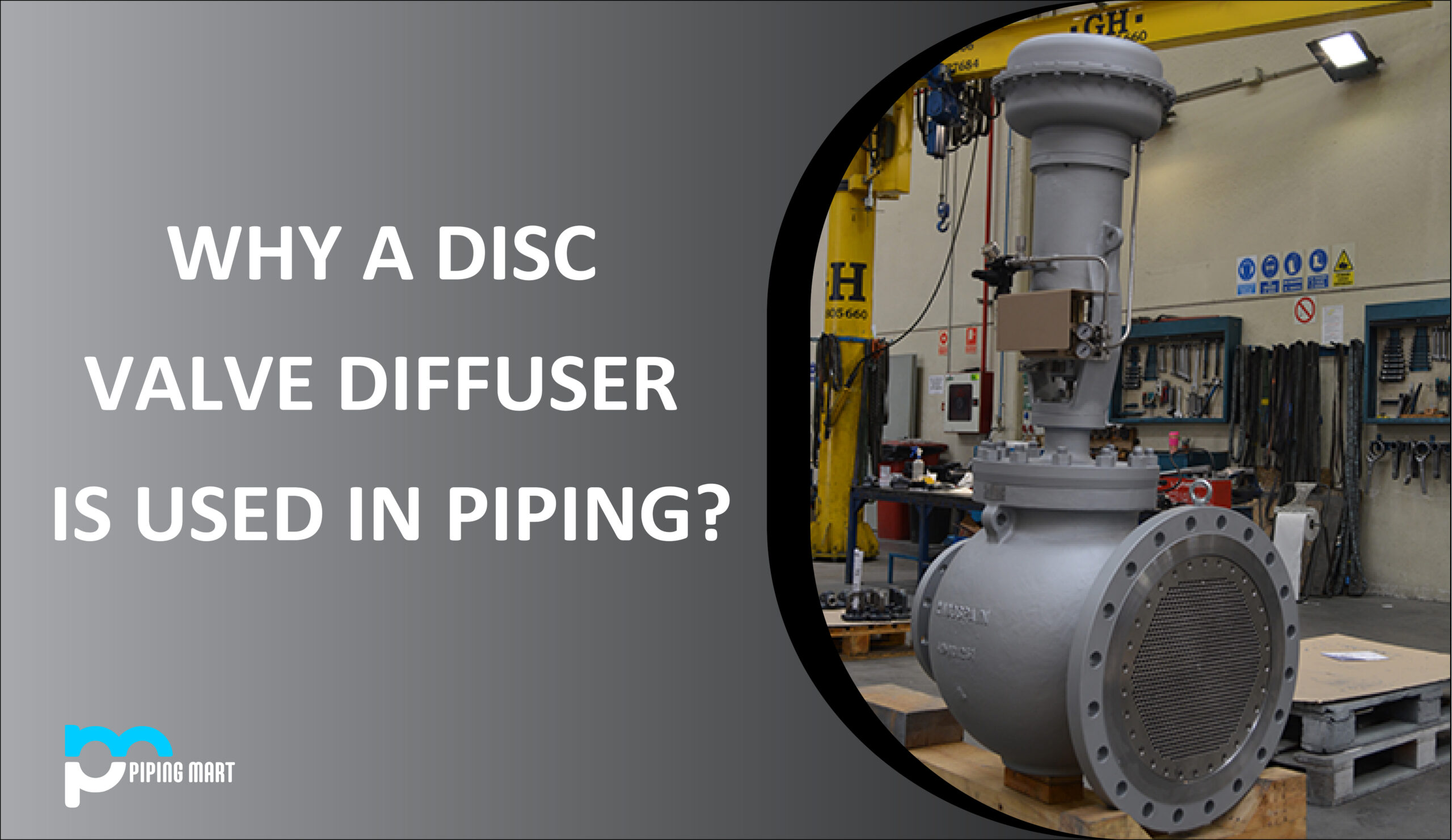
What is a Control valve disc diffuser?
A multi-port plate called a disc valve diffuser is made to meet certain specifications for fluid type, pressure, and noise requirements. The disc diffuser plate may have up to 04 stages depending on the fluid type and pressure drop ratio, while the most typical diffusers have one or two stages.
Stainless steel plates ASTM 304 or 316 are typically used to make diffusers. To absorb 85% of the necessary pressure drop, resistance plates are typically installed downstream of the control valve. Back pressure is applied to the control valve, allowing it to operate within its most productive range.
Resistance plates may be used with diffusers for a variety of reasons. Examples include situations where a valve’s Mach number is too high and needs to be slowed down by applying backpressure through the diffuser plate or when cavitation liquids will make noise or harm the control valve and downstream pipes.
Diffusers also aid in lowering piping system noise levels. That’s why it’s also called a silencer.
Control Valve Mach Number
The ratio of the fluid velocity at the valve outlet to sonic velocity in the fluid at the specified temperature is known as the valve outlet Mach number. It is a crucial factor in determining the valve’s noise level and possible vibration in the valve/pipe system.
Purpose of Control Valve diffuser in the piping system
When a compressible fluid goes through the control valve, there is a significant increase in noise and pressure downstream of the valve, which causes the pipework to vibrate. The piping system may become distorted and damaged due to this vibration. The piping system has diffusers placed to prevent these negative consequences. Diffuser’s primary objectives are:
- Noise level reduction downstream of the control valve.
- Generating backpressure in the control valve’s outflow port.
- Slow down the flow rate out of the control valve.
- Creating a total pressure drop for the control valve’s flow control.
When valves significantly increase noise, a series of inline diffusers provide the most noise reduction. The valve output and diffuser disc face divide the system’s overall pressure decrease during installation. Consequently, the control valve can use a smaller pressure drop ratio. The system’s noise level drops as a result.
Diffuser for Noise Reduction?
In a piping system, a control valve is used to regulate the fluid flow by lowering the pressure of compressible fluids. The pipe system experiences issues with noise and vibration as a result of the pressure drop. That may cause pipes and valves to sustain additional damage.
It is essential to find a solution for these to eliminate the issues caused by noise and vibration. There are two options available to lessen this issue:
To address any noise and pressure decrease in the actual valve body.
To create backpressure downstream of the valve by dividing the pressure decrease into stages.
The issue with the first option is that it will require a large control valve body, which will increase the cost and make the device heavier, complicating maintenance.
Choosing the second approach is, therefore, more cost- and valve-size-effective. In this instance, plumbing has 02 components installed inline. The Control valve is the initial component, followed by a diffuser in the shape of a disc.
Depending on the estimated pressure drop, one or more diffusers may be downstream of the control valve. Due to the increased backpressure brought on by the diffuser control valve, the size can now be decreased. A high pipe diameter is also necessary for the diffuser design to achieve fluid expansion.
Working and Construction of Diffuser
The disc diffuser is built to fit inside a diverging portion installed below the control valve. The gas or vapor exiting the control valve enters the diffuser and travels through a unique configuration of openings in the direction of the piping downstream.
Vibration and noise are produced when fluid with higher kinetic energy departs the control valve. These fluid particles collide with the surface of the disc diffuser, creating a resistance in the flow of fluid that causes back pressure and reduces the fluid velocity.
Due to this, the disc diffuser resistance in the fluid flow route causes back pressure on the outlet port of the control valve and aids in the fluid expanding in downstream pipes. This backpressure aids in more effective valve control to manage the fluid flow.
Difference between Choke Valve and Valve Diffuser
To manage the flow of fluid during the production of oil and gas, choke valves are a form of control valve that has a restricted aperture. The choke valve’s primary function is to minimize pressure loss across the valve while maintaining maximum flow. The flow rate is decreased to prevent cavitation or to lessen the severity of the valve damage.
A diffuser plate resembles a disc with numerous tiny holes in it. It is put in place after the pipe system. A diffuser increases backpressure between the valve and plate and decreases pressure drop across the control valve.
Conclusion
A plate known as a disc diffuser plate is positioned in a diverging area following the control valve. This plate features several holes to lessen the kinetic energy generated following the control valve. The disc diffuser plate produces backpressure, which enhances the control valve’s functionality and lessens the possibility of fluid vibration and noise-related damage.
Pipingmart is B2B portal specializes in industrial, metal and piping products. Also, share latest information and news related to products, materials and different types grades to help business dealing in this industry.