What is steam Heat tracing?
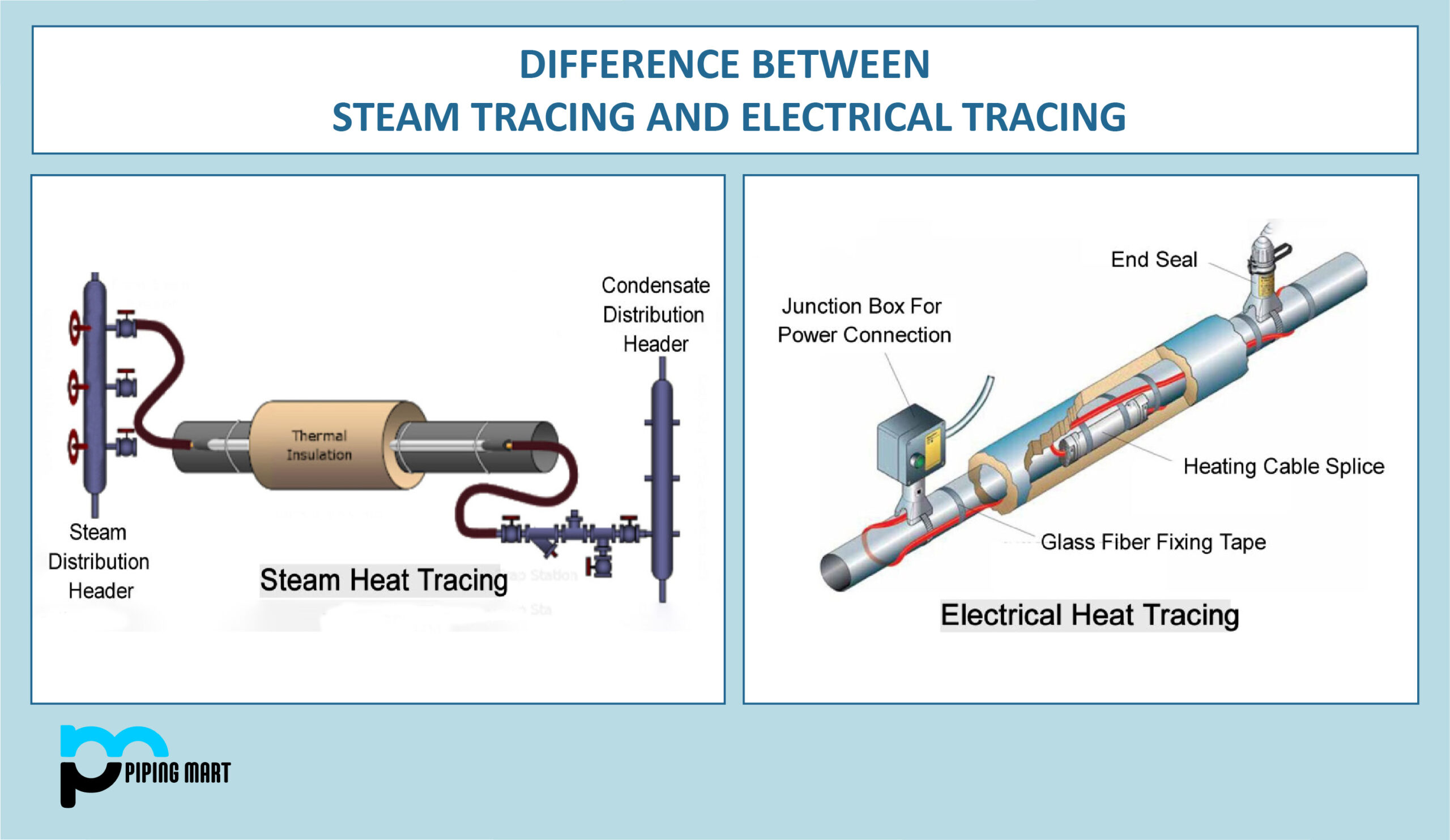
A technique for transferring Heat to pipes with tubes is known as steam tracing, in which high-pressure, high-temperature steam flows alongside a piping network to maintain temperature. An example of a steam tracing system is:
- Tracer Fittings and pipes: for steam flow
- For use and steam distribution on various piping networks, see steam manifold.
- Control valves for steam: for regulating steam temperature and pressure
- Steam traps: For emptying away condensate and separating steam from it.
Definition of Steam Tracing Terms
- To set up or use a steam tracing system, you must be familiar with various terminologies.
- Heat Tracer: A steam-filled tube to convey radiant Heat to the main process pipe.
- Heated Pipe: The primary pipe that is thought to be heated by the heat tracer.
- Air convection tracing transfers Heat through the annular space between heated pipes and thermal insulation.
- The temperature of the surrounding atmosphere is known as the ambient temperature.
- Condensate: Water produced in the Tracer when pipes or other equipment are heated with latent Heat.
- The header for Condensate: The primary conduit for collecting and dispersing condensate.
- Mainline or mother line for the distribution of steam.
- Conduction tracing is the use of a tracer tube that is connected to the main pipe and heated using steam.
- Dry Steam is steam that has no moisture.
- Heat Loss: The rate at which Heat escapes a process pipe through pipe insulation.
- Heat Sink: A pipe system component surface warmer than the main process piping network, such as a flange or valve.
- Heat Transfer cement or heat transfer compound: A heat conductive material with high thermal properties is utilized in heat tracing pipework.
- Heat media: A fluid used for heat transmission that travels via a network of tracer tubes.
- Heat: A procedure where the primary process piping or other equipment needs an extra heat boost.
- Bends or dips in the Tracer could form pockets or closed loops where condensate could gather.
- the minimum temperature necessary to keep process pipes or equipment in place.
- Modular prefabricated steam supply and condensate collecting components made expressly for steam tracing circuits are known as steam and condensate manifolds.
- An automatic device known as a steam trap is used to hold steam in a steam tracing circuit until it has released its latent Heat, allowing condensation, air, and other gases to pass through while keeping steam from moving.
Steam Heat tracing installation
Except for near steam supply and condensate return manifolds, site-fabricated bends are typically used in place of forged elbows. Steam manifolds with built-in glandless piton valves are typically utilized for distributing steam.
Installation of Steam Supply Subheader: To reduce the length of steam supply tracers, the layout of the supply manifold and subheader for steam should be considered. Each subheader shall have a glandless piston valve and a Y-type strainer provided following the appropriate size.
Steam Supply Manifold: In most cases, various locations are chosen to reduce the length of the Tracer. A manifold is needed to distribute steam when three or more tracers are offered.
Steam Tracer Size and Quantity: For heat tracing, typically, steam tracers with a 0.5′′ diameter are utilized. The Main process line needs the following number of tracers:
- Smaller than four ′′ NB: 1 number of Tracer
- From 6″ NB to 16″ NB, use two tracers
- From 18″ NB and upwards, use three tracers
Details of Installation of the Tracer are as follows:
- Galvanized iron wire positioned every meter should hold the tracers in place.
- Heat transfer cement for steam tracing should be applied on a naked tracer to posit the following specifications and requirements.
- A single supply lead line can be directly tapped from the nearby steam header or subheader and routed along the line that needs to be tracked wherever needed in the plant area.
- The tracers must begin at the system’s overall highest point. Tracers should be directed as continuously sloping toward the trap as possible.
- According to the criteria, the total pocket depth of the pocket cannot be greater than the designated depth.
- Instruments and linked equipment must have isolation valves for each Tracer.
- Low point drains shouldn’t be available for Tracer.
- The placement of the tracers should avoid interfering with the regular operation, upkeep, and maintenance of industrial machinery.
- Break flanges at relevant places should be supplied on tracers whenever the traced Piping has flanged connections, and the traced Piping must often be removed for repair, flushing, etc.
- The location of all flange connections on tracers should be outside the insulation.
- When installing, care should be taken to ensure that the supply and return manifolds’ valves, and steam traps are simple to access.
- As much as practical, the lead lines for the steam supply should be routed together. The space between individual tracers may be lowered when multiple tracers are routed to enable box-type insulation.
- The center of the tracer run should have the tracers secured, and there should be enough room around them.
How does steam tracing work?
Steam from the header is supplied to all steam tracers through a steam manifold following the installation of the steam heat tracing system and the primary process piping network. Steam can flow via a Piping network at high, medium, or low pressures, depending on the necessity.
Through radiant heat transfer, the process pipe absorbs the latent Heat of the steam, and the steam trap collects the condensate.
In a nutshell, radiant heat transfer occurs when steam travels from a boiler to a steam header and then to a steam tracer through a steam manifold. Here is how steam heat tracing functions.
Advantages of Steam tracing
When we already know what steam tracing in oil and gas piping or Piping related to any industry is from the upper portion of this essay. We need to be aware of some of the benefits of steam tracing that make it so popular in Piping, including:
- Steam tracers can easily obtain steam in a plant with a boiler. Thus, operational costs are likewise minimal.
- The Steam tracing system will be inexpensive to maintain.
- Due to radiant heat transmission, steam tracing in process pipes is relatively highly efficient with some heat loss.
- Steam is a simple, rapid, and efficient way to get the needed temperature.
- For the dispersion of steam in tracers, no pumping is necessary.
- Excellent temperature management.
- With a steam manifold, steam distribution to various process pipes may be readily managed.
- With steam tracing, a comparatively wider temperature range can be attained.
- Steam tracing generates a significant quantity of Heat that can be recycled in boilers to save costs and increase efficiency.
- Steam generated by condensation can be used again in boilers. Thus, a reusable resource is produced.
Disadvantages of Steam tracing
There are many and varied steam tracing advantages, but there are also some drawbacks, including the following:
- In comparison, installing steam tracers costs more and requires more labor.
- With an industrial site lacking a boiler, the operational cost of steam tracing is significantly higher. They must spend extra money on the boiler’s installation as well.
- need more regular maintenance and checkups.
- Because of radiant heat transfer, it is less effective when heat loss is taken into account while evaluating its performance.
- Steam tracing works best over short distances but loses effectiveness over longer distances.
- Steam heat tracing does not have an even distribution of Heat.
- Since bare tracers are ineffective, insulation is needed to keep the Heat produced in check.
How to calculate pocket depth for steam heat tracing?
The pocket depth is the length of the tracer pipe from the lowest point to the highest position, measured in the direction of the flow. The sum of all the Tracer’s risers represents the overall pocket depth. The maximum total depth of the Tracer should be 40 percent of the gauge press range in meters.
Electrical Heat tracing basics
Electrical heat tracing is heat tracing in pipes where Heat is transferred from the heat tracer to the main process pipe using an electrical element. Due to the Heat tracing cable’s resistive nature, Heat is typically produced here.
A typical heating cable is only one electrical heat tracing system component. The majority of commercial resistive electrical Heat tracing systems are used. The fundamentals of electrical heat tracing are based on Ohm’s Law.
Heat is produced when an electric current passes through the resistive component of the electrical heat tracer. Following Ohm’s Law:
V= I * R and
Heat Output= I² * R
Where I = Amount of current flowing
R = Resistance produced
V = Voltage applied
Power dissipates in the form of thermal energy, or HEAT, in the case of electrical heat resistance.
Electrical Heat Tracing Terms
The following are words typically used in electrical heat tracing:
- Heating cable or Tracer: This is the heat-producing resistive element.
- Pipe Straps: These are used to secure a pipe and an electrical heat tracer in place.
- This is the Tracer’s power input device, the power connection box.
- Junction Box: This distribution box allows for the distribution of several wires to various branches of the piping network.
- A cable tray is a portion of an electrical heat tracing system that aids in supporting, creating room for, and directing the Tracer as it travels away from pipes.
- A Resistance Temperature Detector, or RTD, is an electrical tool that gauges a tracer’s resistance to measure the Tracer’s resistance to Heat.
- Heat Tape: This is a kind of textile tape that can withstand high temperatures. Installing a heat tape with a tracer supports the Tracer with the main process pipe.
- End Joint: When it is a pipe network tracer, a cap with an electrically conductive solution is plugged into it, which forms a complete circuit.
- Thermostat or controller – the device that helps maintain a certain temperature required for a process piping network.
- Terminator: A cable connected through JB or a Power connection box with the help of a gland is called the terminator.
How does electrical Tracing work?
Electric heat tracing often requires one or more cables to facilitate heat flow from all directions, depending on the situation. Using many cables increases reliability because heating can continue even if one of the cables is destroyed. This arrangement will provide maintenance enough time to make the necessary preparations.
Heat is transferred to the process pipe using the radiation method in the electric heat tracing method, although the heat tracer is tightly packed.
The mechanical design of contemporary electric Heat tracing with regulating heating cable frequently modifies the heat output as necessary. Process pipe’s heat regulation is provided by conductive components embedded in a polymer that changes size in response to temperature.
More conductive pathways are created, and resistance reduces due to the polymer contracting and the drop in temperature. More Heat is released when the current flowing through the heat tracer cable increases.
On the other hand, when the temperature rises, poly expands, conductive parts separate, and resistance rises as a result. Due to the reduced current flow in the Tracer, less Heat is generated.
A control and monitoring system can be added to an electrical heat tracing system so that pre-programmed heating sequences, alerts, and other notifications are possible.
Heat Tracing Cable Classification
Heat tracing cable is selected based upon:
The required circuit length
Application of operating temperature
The type of cable best suited for a process pipe network to meet its heating needs depends on the interaction of these two elements. Electric Heat tracing cable comes in three different varieties:
- Self-Regulating Polymer Jacket cables are typically used for circuits with a length of up to 750 feet and temperatures up to 200 C.
- Cable with a mineral insulator suitable for temperatures up to 650 C, with a 3300-foot overall circuit length.
- Systems for skin effect heating cables are designed with significantly longer heating circuits, extending up to 82000 feet and typically producing temperatures up to 250 C.
Parameter to select Heat tracing cable for Piping
Various variables exist for each pipe heating procedure when choosing a heat tracing cable. The following is the Heat tracing cable selection parameter:
- The necessity for Heat.
- The temperature outside.
- Pipe Substance.
- Temperature for Maximum Exposure and Maintenance.
- Supply voltage tolerance and feeding cable voltage drop
- Rated voltage.
- Classification of Area.
- Chemical Ambience.
- Design tolerance.
Piping Heat Tracing Tape or heat tape.
Heat tapes are specifically made to produce Heat when power is passed through them; they resemble electrical extension cords. The following attributes should be included in an industrial heat tracing tape:
- Heat tracing tapes must be flexible to be wrapped easily around pipes or other objects.
- For greater heat transmission efficiency, heat tapes should maintain close contact with the pipe material.
- Heat tracing tapes need to heat up quickly.
- The required temperatures should not be too high for heating tapes.
- Heat-tracing wires or tapes need to be strong and long-lasting.
- For efficient output and heat tape working following points should be followed during the installation of heat tape:
- When being installed, heat tape shouldn’t overlap.
- Before applying the heat tape to the pipe, the surface must be thoroughly cleaned.
- There should be extra lengths of heat tracing tape available for the valve, flange, and other heat sink regions.
Advantages of Electrical tracing
The following are some benefits of electrical heat tracing:
- Electrical Heat tracing employs the conduction technique of heat transfer, but binding to the pipe is very compact, resulting in excessively low heat loss.
- The temperature range is more varied with an electric heating system.
- This is remote-controllable.
- Simple to replace and install during maintenance.
- Energy-efficient.
Disadvantages of Electrical tracing
- Higher maintenance costs.
- The longer the Tracer, the less effective the Heat is
- Where combustible substances are present, installation is not safe.
- System harm could result from overheating if it is not carefully watched.
- To ensure any system failure, multiple tracers are needed.
Pipingmart is B2B portal specializes in industrial, metal and piping products. Also, share latest information and news related to products, materials and different types grades to help business dealing in this industry.