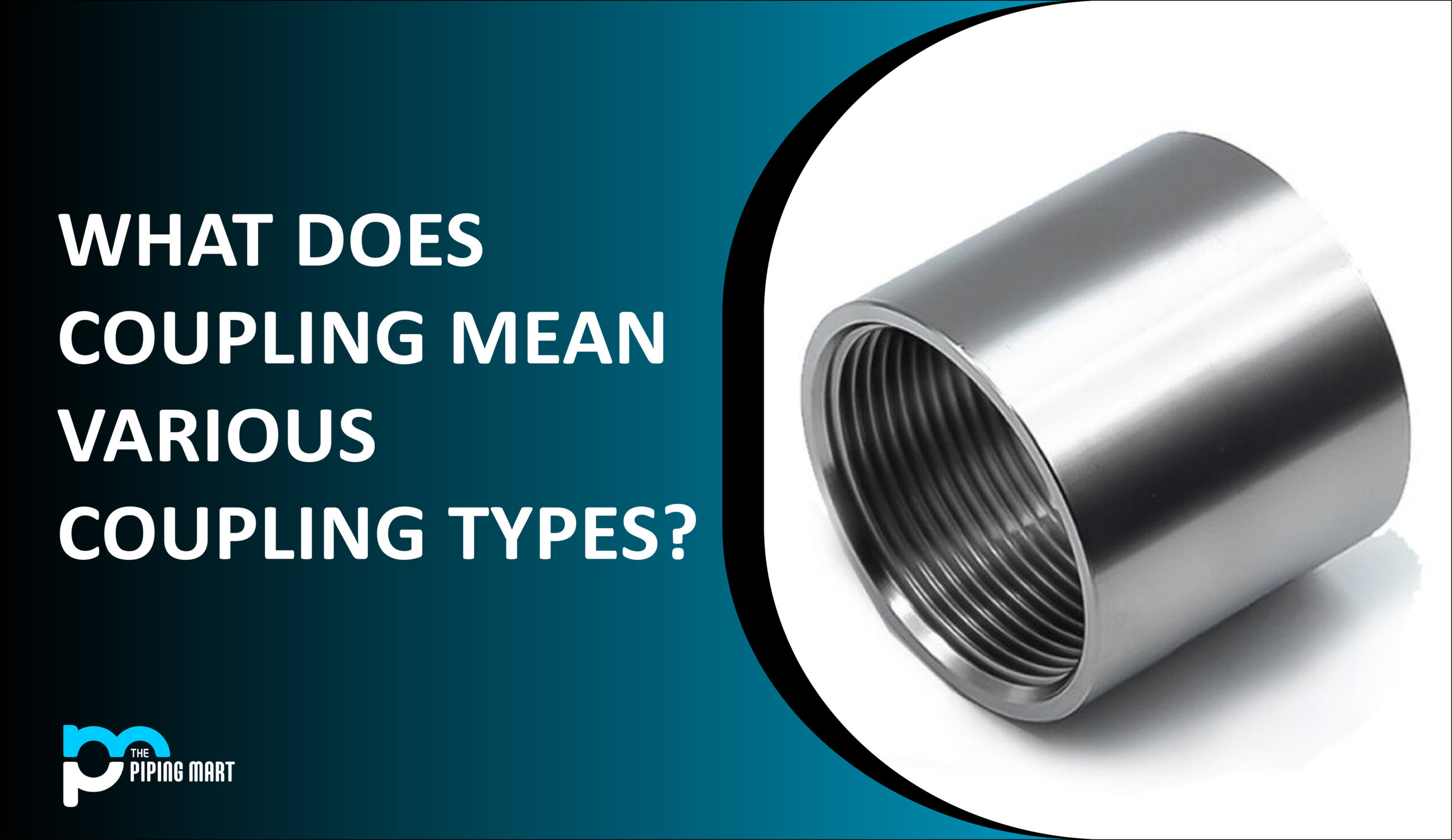
What is meant by coupling?
A mechanical device called a coupling connects one shaft to another. Couplings transmit power and torque in rotating shaft devices like motors, pumps, compressors, and generators. There are numerous designs and operating systems for couplings, each with unique properties and intended uses. Numerous variables, including horsepower, along with load, specific gravity, head pressure, torque, shaft assembly, shaft size, shaft maintenance, safety considerations, etc., affect coupling type design.
What is meant by Shaft Coupling?
The first is referred to as a coupling, and the second is a shaft coupling. A shaft coupling is a machine element that transmits power by joining a motor’s driven shaft and driveshaft. Mechanical flexibility is added via shaft couplings, allowing for tolerance of shaft misalignment. As a result, this connection flexibility helps lessen equipment vibration, uneven bearing wear, and other mechanical issues brought on by misalignment.
By conveying torque while correcting for parallel, angular, as well as axial misalignment between drive components, flexible shaft couplings can help avoid these problems. Flexible shaft couplings can protect driveshaft components, minimize noise, and reduce vibration when placed properly.
Shaft couplings transmit power and torque in rotating shaft devices like motors, pumps, compressors, and generators. A large casting type is available for large power transfers like those found in wind and hydraulic power machinery. A tiny shaft coupling is mostly used for FA (factory automation).
What are the different types of coupling?
The three types of couplings used to transmit power are rigid, flexible, and fluid, depending on the alignment accuracy of the system and the required torque. Even though each coupling type has benefits and drawbacks, it’s crucial to determine which to use in a certain application. We detail the construction and functionality of several coupling types because they are rather distinctive.
Rigid Coupling:
Couplings provide a strong, precisely aligned connection between two shafts. In the past, rigid couplings were inexpensive and frequently made-at-home components for simple shaft-to-shaft connections. A coupling must permit no more than one degree of deflection or even an angular movement to be considered stiff. Since this kind of coupling lacks flexibility and robustness, good initial alignment of the shafts and stable support bearings are required to ensure good performance. It needs to be straight both laterally and angularly to prevent transmission damping, installation breaks, excessive stresses on the shafts, and shaft bearing damage.
Rigid couplings are the most effective for high-torque demands, shaft support applications, and push-pull use cases. These couplings are utilized when a rigid union, akin to a conventional flanged, welded, or threaded connection, is sought.
Characteristics comprise:
- The two shafts of the loading time must be perfectly coaxial. They can accommodate a little hub misalignment of 5 mm and a precision shaft misalignment of up to 0.5 degrees. The radial pulse is less than 0.03 percent, and the maximum axial core tilt is 0.05/1000.
- Because of their benefits, rigid couplings are frequently used for projects.
- One of its main features is the coupling’s ability to effectively transfer torque from one shaft to the other connected shaft.
- Rigid couplings are readily available from manufacturers in both standard and customized models, with almost no windup and no backlashes, and with precision.
- Better placement is possible in this coupling due to the high torsional rigidity.
- It can be used to determine the shaft alignment between the linked components and the motor.
- Simple construction, disassembly, and maintenance procedures are possible throughout the coupling’s lifetime.
Although various advantages are present, there are some drawbacks included. These are:
- They are unable to adapt to any heat variations.
- Compared to flexible couplings, their applications are more constrained.
- They can’t absorb vibrations.
- They frequently need lubricating.
- They cannot be maintained at extremely high RPMs.
Sleeve or muff coupling:
The simplest sort of stiff coupling is the muff or sleeve coupling, which is constructed of cast iron. A shaft, along with the key, sleeve, or muff, and a hollow cylinder with an inner diameter equal to that of the shaft, form a muff coupling. With the aid of a gib head key, it is secured over the ends of the two shafts.
A key and a sleeve are used to transfer power from one shaft to another. To transmit the torque, all of the components must be powerful enough.
Clamp or split-muff or compression coupling:
It also goes by the name “split muff coupling.” The muff or sleeve is divided into two parts and welded together in these connections. Cast iron makes up the pieces’ halves. Studs or bolts are used to attach them. The ends of both shafts are joined together, and each shaft has a keyhole that accepts a key. The muff’s other end is fastened from above, and one end is fixed from below. Bolts and nuts hold both of them together.
There is a lot of application for this coupling at heavy-duty speeds. The shaft’s position must not be altered to build or disassemble the connection.
Flange coupling:
A flange coupling is a driving coupling used to connect two spinning shafts. One flange is set at the end of each shaft, and the other two flanges are joined by a ring of bolts to form the drive.
This style of connection is designed to flush-seal two tube ends together. To marry the opposite tube end, which also has a flanged end, to the flanged end of this two-piece coupling unit, the flanged end must be connected to the keyed receiving side. Each flange includes a male or female coupler aperture to align the two ends without creating resistance or drag in the material being passed through them.
The flange coupling is kept firmly in place by this male or female coupling technique, which also generates a connection that is stable and resistant to movement.
Pressurized piping systems frequently use flange couplings when two pipes or tubing ends need to connect. Due to the pressure of the material or the occasionally hazardous nature of materials conveyed via many industrial piping systems, flange coupling connection methods are typically highly robust.
The flange couplings are fastened in place using nut and bolt connectors with a high thread count. To give long-lasting strength and the capacity to be tightened to the maximum degree to ensure the piping system doesn’t leak at any flanged junctions, these nuts and bolts are often produced from tempered steel or alloys.
Most flange couplings use four, six, or even twelve-bolt assemblies.
The three different kinds of flange coupling are as follows:
- Type flange coupling without protection.
- Flange coupling of the protected type.
- Coupling of the marine type.
Flexible coupling:
It is used to join two shafts out of alignment laterally and angularly. 90% of couplings supplied are flexible, which allows for radial, axial, and rotational movement and torque transmission between two shafts when they are slightly out of alignment. A coupling must accommodate parallel and angular misalignment to be deemed flexible. These couplings also aid in providing a nearly smooth transmission of speed and torque by bending themselves to reduce the transfer of fluctuation of torque and speed from one rotor to the other.
Flexible couplings can be used in servos with low or moderate torque levels and the possibility of shaft misalignment. We can get various torque capacities depending on the kind of flexible coupling. These types of coupling are employed when applications require curved or deflected architectures, when systems are subjected to external forces outside typical static circumstances, such as seismic events, or when vibration attenuation or noise reduction are important considerations.
Applications:
Manufacturing of semiconductors, packaging technology, and machining tools. Examples include:
- The bushed pin-type coupling.
- The universal coupling.
- The Oldham coupling.
- The gear coupling.
- The bellow coupling.
- The jaw coupling.
- The diaphragm coupling.
Characteristics include:
- Flexible coupling can allow a small angular misalignment of up to 1.5 degrees and an axial misalignment of up to 5 mm between different loads and shafts.
- They are constructed from a solid metal piece.
- They frequently contain more parts and are more complicated.
Advantages can be seen as:
- They make up for deflection, movement, or misalignments.
- They come in quite handy for quick and brief starts.
- They have excellent shock or vibration transmission reduction capabilities.
- Disadvantages comprise:
- They typically transfer torque less effectively.
- They are expensive because they have extra pieces.
- They don’t eliminate backlash.
- Their upkeep and operations are more difficult.
Bushed pin-type coupling:
This is used to adjust the two shafts’ axial, angular, or slightly parallel misalignment. This has modified the rigid flange coupling. It comprises two parts with different constructions, two pin-like bolts, and rubber bushes utilized in place of the pins. Between the faces of the coupling’s two sides, there is a 5 mm gap. There is no fixed connection between them and the drive-through compressed leather or rubber bushes.
Universal coupling:
It is applied when the axes of two shafts cross at a little angle. The inclination of two shafts can remain constant, but in reality, this is altered whenever motion is passed from one shaft to the other.
The image above depicts a universal joint. These couplings are frequently utilized in power transmission. A car’s transmission, which connects the gearbox to the differential, has universal coupling. Two universal joints are utilized on each end in these circumstances. One on the differential to one end and one at the gearbox’s end of the propeller shaft. Additionally, power is transmitted to various spindles of numerous milling and drilling machines using universal coupling.
Oldham coupling:
If there is a lateral misalignment between two shafts, an Oldham coupling is used. Oldham coupling’s schematic diagram is shown in the image below. It comprises a center floating section E with two tongues, T1 and T2, and two flanges, A and B, with slots.
Pins attached to flanges and floating components fix the central portion. The T1 tongue mates with flange A to provide the backward and forward motion, while the T2 tongue mates with flange B to permit vertical movement of the pieces. The lateral displacement of the shaft will be corrected as they spin as a result of these two-speed factors.
Gear coupling:
The flange coupling has been updated to become the gear coupling. Instead of being assembled as a single piece like in a flange coupling, the flange and hub are individually assembled in this form of shaft coupling. Due to the teeth’ huge size, gear couplings can transmit significant torque.
Each joint in the structure features an internal and external gear pair with a 1:1 gear ratio. Additionally, gear coupling can only correct angular misalignments of up to 2 degrees and 0.01-0.02 inches in parallel. Universal joints and gear couplings are both employed in related situations. These are frequently employed in load-bearing applications where a lot of torque must be transmitted.
Bellow coupling:
Bellows couplings are flexible couplings having what is known as hub-like twin coupling ends. Excellent torsional rigidity allows these couplings to precisely communicate torque, angular position, and speed. Wherever high-precision positioning is necessary, these couplings are used. Stainless steel is typically used to construct them.
Bellows coupling has minimal flexibility for axial, parallel, or angular misalignment and is made up of thin walls. The hubs and coupling bellows are joined by welding. These couplings have the highest torsional stiffness of any servo motor coupling.
Jaw couplings:
This coupling is employed in motion control applications in addition to general-purpose power transmission. The jaw coupling’s purpose is to deliver torque while minimizing system vibrations and correcting misalignment, safeguarding other parts from harm.
A jaw coupling consists of two iron hubs and an element, sometimes known as a “spider,” made of Elastoplast.
Jaw coupling has the benefits listed below:
This system is capable of handling reactive loads brought on by angular misalignment.
They are capable of an excellent torque to the outside diameter.
Excellent chemical resistance and respectable damping capabilities.
Diaphragm couplings:
One type of non-lubricated coupling used in greater-performance turbomachinery to transmit torque and correct equipment shaft misalignment is the diaphragm coupling.
This kind of coupling transfers torque first from the outside to the inside and subsequently from the inside to the outside.
A single plate or a set of plates is used for the flexible parts in diaphragm couplings. Misalignment can be axial, parallel, or angular with diaphragm coupling. This connection is utilized when strong torque and rapid speed are required.
Fluid Coupling:
Another name by which fluid coupling goes is hydraulic coupling. It is a hydrodynamic device that uses the acceleration as well as deceleration of hydraulic fluid to convey rotating mechanical power. It comprises a runner on the driven shaft (output) and an impeller on the driving shaft (input). The runner functions as a turbine, and the impeller as a pump. Both have a fluid inside. Often oil is injected into the coupling via a filling plug on the housing. The most common metallic materials used to make fluid coupling parts are aluminum, steel, or even stainless steel.
The tangential component of actual or absolute velocity is small in the impeller close to its axis. When the impeller accelerates, the fluid velocity rises because the tangential component of actual velocity is high at the near perimeter.
Kinetic energy increases as velocity does. The fluid exits the impeller at high speed, hits the runner blades, exchanges energy, and exits the runner at low speed.
The manufacturer can benefit significantly from these couplings in a variety of power transmission scenarios. A fluid coupling provides the benefits of a gentle beginning of the load, torque limiting, and mechanical shock absorption, all with minimum energy loss, as a means of conveying rotational mechanical drive power. They are helpful when a program calls for variable speed operation and a system beginning without a shock.
Application:
The transportation, mining, aerospace, and railroad sectors. Pumps of all kinds, forklifts, cranes, mining equipment, diesel trains, airplanes, rotationally powered industrial equipment, belt conveyors, extruders, centrifuges, bucket elevators, compressors, shredders, blenders, slurry pumps, condensers, industrial fans, feeders, diesel locomotives, wagon tippers, boiler feed pumps, reciprocating pumps, process pumps, dryers, etc.
Characteristics are:
- Scoop tube-type fluid connections have a step-lesser change in speed.
- The driving and driven shaft are not in mechanical contact (or between the pump wheel and turbine wheel).
- Performs operations in both horizontal and vertical applications.
- A motor or engine can start with no load, regardless of machine load.
The various advantages can be:
- Multiple motors are started sequentially to lower the total amount of electricity drawn.
- A straightforward squirrel cage induction motor allows for big inertia-driven machinery’s smooth and controlled acceleration.
- Lower capital costs are achieved by motor selection for running duty/load instead of starting loads.
- By restricting the maximum torque to a specified safe amount, overload safety is provided for the driven and motorized machinery.
- High efficiency because of the rated duty’s low slip.
- Power transfer happens smoothly. Controlled acceleration without subjecting the power transmission system to shock loads.
- The input and output elements do not wear out from friction because there is no mechanical connection between them.
- Effective damping of torsional vibrations, load variations, and shocks. Even under harsh circumstances, the fluid coupling can function properly.
- There are no vibrations during the power transmission. When power is transferred from the oscillating engine to the driven shaft by using a fluid coupling, there is no risk of vibration noises.
- When a fusible safety plug responds (blowing off) to a persistent overload, the prime mover automatically unloads.
- By adjusting the fill level, torque may be controlled easily. The maximum torque can be changed by adjusting the amount of operating fluid inserted into the casing.
Drawbacks can be noted as follows:
- When the driving and driven shaft rotate at the exact angular speed, it cannot produce torque.
- Slip happens occasionally. The speed difference between the turbine wheel and the pump wheel is constant.
- The fluid-filled enclosure and coupling component must be compatible since it directly impacts how the fluid coupling transmits power.
- The coupling loses energy as heat when it stalls, which could cause harm.
Beam coupling:
A flexible coupling known as a beam coupling or helical coupling is used to transfer torque between two shafts while allowing for axial motion, parallel offset, and a shaft’s angle-oriented dislocation about another.
A single piece of material rendered flexible by material removal in the form of helices throughout its length makes up a beam coupling. The goal of a beam coupling is to transmit torque between two shafts, as it is with all couplings, but unlike a rigid coupling, it can take into account angular misalignment, parallel offset, and even axial motion of one shaft concerning the other.
The beam coupling differs from other forms of coupling in that it is made of a single component, which eliminates the backlash typically experienced by couplings consisting of many parts.
Several materials can be used for beam couplings, including titanium and acetal, but the two most used are stainless steel and aluminum. Aluminum beam couplings are suitable for applications requiring a high degree of responsiveness because of their lightweight.
While offering more strength and torsional rigidity, stainless steel does not have the same reactivity due to its higher mass.
Disc coupling:
By definition, a disc coupling transmits torque tangentially on a shared bolt circle from a driving to a driven bolt or shaft. A pack of thin stainless steel discs used in succession transmits torque between the bolts. Deforming the material between the bolts causes misalignment. This kind of coupling is a higher-performance motion control coupling made to act as the element that transmits torque while compensating for shaft misalignment. Under high torque loads, it is intended to be flexible while continuing to be torsionally strong. Disc couplings can typically manage rates of up to 10,000 r/min.
The two types of disc coupling are as follows:
Single-disc style couplings consist of a single, flat stainless steel disc spring and two hubs, which are the ends of the coupling and are normally made of aluminum; however stainless steel is another option.
Although two hubs make up a double-disc style coupling, the two-disc springs are sandwiched between an additional center spacer. The hubs’ center spacer can be composed of the same material, although insulating acetal is occasionally offered, making the coupling electrically isolating.
Disc couplings are a fantastic option for high-speed applications since they are both torsionally rigid and nevertheless flexible. The drawback is that they are more brittle than the typical connection and are susceptible to harm if not handled properly. Further care should be exercised to ensure that dislocation or misalignment is within the coupling’s ratings.
Grid Coupling:
Grid couplings are made with high torque density applications in mind, just as disc and gear couplings. Grid couplings are ideal for applications requiring shock loading and are frequently made up of two shaft hubs, a horizontally split cover kit, and a serpentine grid.
The shock-absorbing grid relieves shock-loading applications while the grid element transmits torque between the two shaft hubs, decreasing the linked equipment. With the right setup, upkeep, and lubrication, your operation can receive years of dependable service.
Grid couplings are a flexible, established technology with easily available interchangeable parts from several significant coupling manufacturers.
Grid couplings are generally easy to install and have a high power density (they transmit a lot of torque compared to their size). They come in both inch and metric bore sizes and have strong resilience to environmental factors.
Roller-Chain Coupling:
A roller chain coupling is a mechanical component of two altered sprockets and a double-strand roller chain. It consists of a sturdy chain and precisely cut, hardened-tooth sprockets that deliver a significant amount of torque. Despite its small size, the design is straightforward and extremely efficient.
Although very straightforward, roller chain couplings offer a small, flexible connection appropriate for a broad range of applications.
The coupler has an even amount of torque dispersed throughout it when it is moving, thanks to the design, which distributes the torque throughout the roller chain and sprocket teeth.
A roller chain coupling’s minor space created by the sprockets and chain means that complete shaft alignment is not necessary for the coupling to work, though it is still strongly advised to have the shafts precisely aligned if at all possible.
Tire Coupling:
Tire couplings are torsional soft shaft couplings that adjust for misalignment and safeguard other transmission system parts. They have flexible bodies.
Tire couplings have a low torsional backlash and are very flexible. Couplings are particularly well suited for coupling machines with a highly nonuniform torque pattern due to their low torsional rigidity and dampening capacity.
The use of these tire couplings for connecting machines with significant shaft misalignment is also appropriate. The elastic tire can easily cover the hub components. The elastic tire is tightly held in position by putting the clamping ring in place.
Through frictional engagement, the connection transmits the torque. Standard tire coupling types are intended to connect two shafts. On-demand, application-specific types can be implemented. The connection can have elastic tires made of natural rubber installed for ambient temperatures between -50°C and +50°C and elastic tires made of chloroprene rubber for temperatures between -15°C and +70°C. The “Fire-resistant and Antistatic” (FRAS) marking is on the chloroprene rubber tire.
Reduces the transfer of vibration or shock loads.
High potential for misalignment
Simple assembly without relocating hubs or attached equipment
High-speed to moderate operation
Various torque capacities
What are the Conditions For A Good Coupling?
- The following characteristics of a good shaft coupling should be present:
- Connecting and disconnecting should be easy.
- It must safely transfer all of the power from one shaft to another.
- It ought to maintain the shaft’s proper alignment.
- The propagation of shock loads from one shaft to another ought to be reduced.
- It shouldn’t have any elements that project.
How to check Coupling Maintenance And Failure?
- Each coupling must be inspected regularly as part of coupling maintenance. It includes:
- Performing visual examinations, looking for wear or fatigue, and routinely cleaning connections. If the coupling is lubricated, check it frequently and replace the lubricant. Most couplings need this maintenance once a year, while couplings in harsh locations or under difficult operating conditions need it more regularly.
- Keeping a record of the upkeep done to each couple, along with the date.
- Couplings might nevertheless fail even with regular maintenance. Other than maintenance, the following are the underlying causes of failure, faulty installation, poor choice of partnering, or operation beyond the scope of the design.
- Understanding the root of the failure and fixing it before installing a new coupling is the only method to extend the coupling life. External warning indications of possible coupling failure include some of the following:
- Unusual sounds include chattering, shrieking or squealing, excessive trembling, and tremors.
- Leakage or contamination of the lubricant is a sign of failed seals.
Pipingmart is B2B portal specializes in industrial, metal and piping products. Also, share latest information and news related to products, materials and different types grades to help business dealing in this industry.