What is a Pneumatic Valve?
A pneumatic valve, commonly referred to as a directional control valve, is primarily used to change the airflow direction. These valves can keep the pressure constant. There are numerous categories and a wide variety of pneumatic valves available. The style, kind, design principle, mode of operation, function, size, and application of pneumatic valves are classified. The pneumatic valve can perform various tasks, from turning on and off a single flow path to precise proportional control of pressure and flow. Most pneumatic valves have a control function, defined as the valve operating in any process or controlling a quantity. One can determine the control energy by the mode of actuation, which can be manual, mechanical, hydraulic, or even pneumatic. A control function requires control energy.
There are often two distinct usage situations for the term “pneumatic valve” that require clarification. A pneumatic valve is a device used to modify or regulate the flow of air (or another gas) in a pneumatic system in the first instance. They regulate air or gas entry into the pipes, tubing, or equipment in an automatic pneumatic system at the source, as needed.
Several methods, including manual, mechanical, pneumatic, and electrical, via a solenoid or motorized actuator, or manually, may be used as the actuation element to cause the pneumatic valve to open or close. The critical notion in this illustration is that the pneumatic system manages and delivers pressured air or gas through the valve ports.
In the alternative situation, the air is used to operate the valve. Still, another fluid, possibly water, oil, or another, is flowing through the ports of the valve instead of air. The pneumatic valve, in this situation, controls the flow of a valve, but the fluid in the lines is not air. The pneumatic actuator uses air as the control fluid to open, close, or adjust the flow. As a result, these valves are known as pneumatically actuated valves.
In the first situation, the air is controlled but may or may not act as the valve’s control mechanism. In the second instance, a fluid other than air is regulated, and the air is the controlling factor. Understanding pneumatic valves and their applications will be improved by making a difference between these two dominant settings. The several kinds of pneumatic valves are typical examples of the first situation.
Designations and Configurations of Pneumatic Valve
The criteria known as ports, switching positions, and non-actuated state are reflected in numerous valve designs under the widely used classification of pneumatic valves, such as two-way, three-way, and four-way. These configurations are often defined using a standardized numbering system, which includes two numbers segregated by a slash (/). The first number represents the valve’s port number, and the second represents the quantity of switching positions. A 2/2-way pneumatic valve is an example of a device with two ports and switching positions. A three-port, two-position valve is referred to as a 3/2-way valve. The subject of the non-actuated state is another one of these options. It is possible to prepare a 2/2-way valve in both the generally closed and generally open positions.
Normal closed refers to the valve being closed and not allowing air to travel between the ports when it is not being operated. The valve needs to be actuated to open. The opposite is true for typically open valves. Airflow is allowed through the valve without actuation, and the valve must be actuated to close. One port is usually open in three-way valves. In these situations, the airflow port is often blocked by a closed resting state, preventing airflow until the device is turned on. For instance, a five-port, three-position valve contains ports 2 and 4 for exhaust, 3 and 5 for work, and 1 for pressure inlet. Regularly used pneumatic valve arrangements include 5/2, 4/2, 3/2, and 2/2.
There are pneumatic valves with spring offsets or detents. When the actuation is removed from spring offset valves, the valve returns to the initial state or condition. Detented valves maintain the last actuated position until the operator changes it again.
Specifications of Pneumatic Valve
Pneumatic valves are subject to many standards, some of which are reviewed here. Consumers should be aware that each valve manufacturer and supplier may characterize their valves differently and that these characteristics are just meant to serve as general guidance. Additionally, the precise specifications depend on several factors, including the intended porting, the manifold design, and the valve actuation mechanism.
The amount of pressure or range of pressures that the valve is designed to withstand is known as the operating pressure or pressure range (in psi, Bars, or Pa)
The many types of fluid that the selected valve can safely manage serve as its operating medium. It is compressed air in most devices.
A measure of a valve’s ability to pass or flow air through it, flow capacity or the flow coefficient (Cv) expresses the proportionality constant among flow rate and differential pressure.
Response time is the amount of time required for an actuated valve to change states or positions.
Cycle rate is the maximum number of cycles a valve may perform in a given time.
Coil-rated voltage, measured in both DC and AC volts, is the maximum voltage an electrically operated valve’s actuation coil can produce.
Port size: The equipment’s port sizes and thread style are determined by the physical dimensional characteristics.
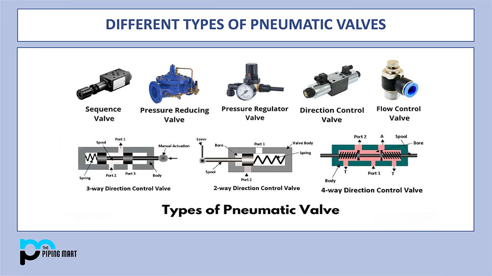
Types of Pneumatic Valves
Pneumatic valves are set up in a variety of ways, including
Along with the number of flow paths or switching positions that are available;
By the number of inlet and output ports they have;
And the mechanism used to open or close the ports depends on the valve’s condition when it is not in use.
Directional Control Valves
Available directional control valves, or those that guide airflow or completely stop it, are a broad category of pneumatic valves that include a variety of subtypes. These components can be utilized in a hydraulic system in various ways, such as to advance or retract air cylinders that are part of the machine or process for which the pneumatic system was designed or to connect or disconnect the system’s primary compressed air source.
In light of this, the main categories of pneumatic valves under directional control can be broadly classified as follows:
Valves with two-way directional control
Pneumatic three-way directional valves
Four-way pneumatic valves with directional control
Pneumatic spring-offset valves
Directional control valves are essential components in every pneumatic circuit to manage the speed or order of operations. The flow routes under different operating conditions can be used to categorize directional-control valves. The number of ports and flow routes, as well as the number of potential valve settings, are significant determinants. Here are a few basic setups.
Two-way, Two-Position Valves:
These contain two ports joined by a passage that may be opened or closed to control the flow through the valve. In most cases, a solenoid that is electrically operated changes the valve’s spool or poppet to guide the flow. Many systems employ the valve’s simple on-off function to connect, interlock and isolate different system components.
Three-Way, Two-Position Valves:
They are comprised of a valve body and three ports connected by passageways. The valves pilot another valve or pressurize and exhaust one output port to regulate a single-acting cylinder. Pressurized air is sent to the cylinder’s cap-end side by three-way valves. Moving the spool to the other extreme prevents flow and pressure from reaching the actuator. Since the actuator is attached to the exhaust tube, the rod must return to its initial position by gravity or spring force. A pair of three-way valves can operate a double-acting cylinder instead of a four-way valve. When high cylinder speeds are required, think about employing paired three-way valves as an alternative to a four-way. Higher cylinder velocities are made possible by reducing cylinder backpressure and pressure drop in the lines by tightly attaching three-way valves to the cylinder ports. In high-cyclic applications or where intermediate locations are necessary, the valves are also employed to conserve compressed air.
Four-Way, Two-position Valves:
They have two or three places on each of four or five ports. An actuator, rotary actuator, or bidirectional motor can be activated and reversed using a two-position valve’s two different flow channels in each position. The other actuator port simultaneously exhausts to the atmosphere as the spool controls flow from the pressure port. The four-way valve of the two-five-port position’s variant features five distinct ports that allow for various valve combinations, including two distinct exhaust or pressure ports. For instance, in the latter scenario, the valve may deliver high pressure to activate a cylinder and create a strong clamping force but lower pressure (from a regulator) to release the clamp. Lowering the pressure saves energy.
Four-Way, Three-Position:
There are other five-port versions of valves available. The two most typical center situations for these valves are “exhaust center” and “all ports shut.” The four-port, four-way valve’s power positions, which regulate actuator movement, are located in its two extreme positions. The center position is intended to meet system needs, including locking or floating an actuator.
Spring Offset Pneumatic Valves:
This type of pneumatic valve categorization is referred to as the method of changing the airflow direction. For instance, a two-way directional valve has two possible states: open (enabling airflow) and closed (preventing airflow) (airflow is prevented). An actuator positions a valve spool such that each port assumes an open or closed position. A spring releases the valve spool, allowing the pneumatic valve to revert to its original position. This type of two-way directional valve is also called a spring offset valve.
Non-return valve
These valves are similarly used to regulate airflow; however, they only permit airflow in one direction, permanently blocking airflow in the opposite direction. These valves are constructed so that the downstream air pressure loads the check, supporting the non-return action. Certain non-return valves, such as check valves, shuttle valves, rapid exhaust valves, and two pressure valves, can perform pneumatic controls.
Flow control valves
This valve can control airflow. However, the control is only effective when the airflow through the valve is open and maintains a specific volume per unit of time.
Pressure control valve
Pressure control is possible with pneumatically operated control valves because they regulate the air pressure inside the valve. In essence, these valves can alter the pressure of airflow in valves. There are three pressure control valves: pressure limiting, pressure sequence, and pressure lowering.
Types of Pneumatic Valves based upon the Actuators:
The many types of actuators that pneumatic valves employ can be used to classify them. They may be equipped with mechanical, air-operated, or electromagnetic actuators.
Solenoid Valves:
Solenoid valves respond to an electric signal by opening and closing. They regulate liquid flow in a hydraulic system and air in a pneumatic system. A valve with a spool or poppet arrangement is an option.
Solenoid valves are typically utilized in industrial manufacturing settings. The valve requires a constant temperature to function effectively. The valve must be able to withstand temperature variations to prevent shorting out if there is a need for one to function in a continually shifting environment. For instance, the latter can be seen when the ignition is started in an automobile. An electric signal is sent when the driver turns the key to open the valve and start the engine. The valve must manage the engine’s heat and any cold from lousy weather.
Regarding their use with fluids, other solenoid valve uses include irrigation systems and dishwashers. They regulate the water flow so that it can be used to wash the glasses and plates or to regularly water fields. The adaptability and toughness of these variants are well regarded.
Air-Operated Valves:
From a design perspective, air-operated valves resemble solenoids in shape. However, they react when air pressure exerts a force on a piston or a diaphragm rather than in response to an electric signal.
In settings that require high output but don’t want to rely on electricity and who want to utilize them remotely, air-operated valves are seen. Thus, they are employed in factories that produce fertilizer and chemicals. Regarding the former, chemicals might cause combustion and put their operators at risk if they are subjected to improper ingredients. People are kept away from possibly harmful nitrogen molecules in the latter.
Mechanical Valves:
Manual power is used via mechanical or hand-operated valves. They may be used in situations when electricity would be risky or useless for the job at hand. They can be used for liquid or air movement, similar to solenoid valves.
These valves are often moved by applying force with hands or feet. The user would have to push a button with their hand or push-pull. Lever arms or friction are used to power other varieties of mechanical valves. Modern mechanical valves need to be larger in size to manage a higher flow rate.
The mechanical valves used to treat heart problems are one illustration. They contribute to ensuring that the human body receives enough blood and oxygen. These mechanical hearts improve a person’s longevity while also increasing the risk of blood clots.
A manual valve utilized in an outdated device without an electrical connection would be another example. Consider how an individual would press a pedal to operate vintage sewing machines and spinning wheels; the energy would be transferred in a circular motion. They would employ simple pneumatics.
Working Principle of Pneumatic Valve:
The primary responsibility of the pneumatic distributor is to modify the cross-section of the pneumatic pipeline so that the flow can be adjusted and directed.
The locking and regulating components carry out this function. Section changes might be discontinuous (on/off) or continuously smooth (with adjustable parameters).
Due to this purpose, there are two primary structural kinds of equipment piston and spool.
Piston valves are made for controlling distinct flows of fluid. The channels can be quickly isolated with this kind of management. It is best suited for compact systems with specific functions. Along the flow line, the valve seat is in motion. Such a design often only has two or three outputs.
Sliding spool valves are made to perform more intricate flow control procedures. That machinery is suitable for circuits with intricate cross-sections and significant flow rates. Spool valves are versatile and can operate in circuits with 4-5 working lines and simpler ones. Moving perpendicular to the flow axis is the spool.
How does a Pneumatic Valve work?
Compressed air pneumatics systems need particular actuator control strategies for safe and accurate operation. Even though the medium is fluid, like hydraulic or process water systems, the way control is significantly implemented from how it would in a liquid. All fluid power mediums that carry fluid motion require valves to regulate force, velocity, and direction of motion.
Air preparation:
By expelling pressure into the atmosphere, pressure relief valves regulate pressure at their inlet port. Solving valves usually are only employed in receivers or air storage devices like accumulators to avoid over-pressurization. Relief valves, also known as safety valves, are usually only applicable during air preparation. In pneumatic systems, pressure regulators control downstream pressure by preventing upstream pressure at the inlet. Regulators are used to controlling cylinders and motors as well as to prepare the air for usage. The regulator, denoted by the letter R in the FRL acronym, is situated downstream of the receiver tank but before the circuit whose pressure it regulates.
When a sizable centralized compressor and receiver serve numerous workstations, it is sometimes necessary to reduce pressure in more than one stage. Most regulators can release downstream pressure, which stops that pressure from rising due to load-induced pressure or thermal expansion.
Regulators are typically sold as a part of modular sets that include a filter, another regulator, a lubricator, a dryer, etc. These sets can be put together in any order. The regulator will have three ports: one for the input, one for the outflow, and one for the pressure gauge, which is most frequently incorporated.
Individual actuator pressure can also be regulated via pressure regulators, such as inline and work-port mounted regulators. These are frequently relatively tiny and come with reverse flow check valves, as would be necessary, for instance, for a cylinder to run in double action. Furthermore, some manufacturers offer differential pressure regulators, which go beyond simply maintaining downstream pressure to maintain a predetermined pressure differential between the two ports. All pressure regulators can be adjusted, most frequently using screws or knobs. It should be mentioned.
Flow controls:
Pneumatic systems frequently use flow control valves. Flow valves are less standard than pressure or directional valves, although most circuits use them to facilitate simple cylinder or motor velocity adjustments. Pneumatic systems require more intricate velocity control than hydraulic systems because a cylinder’s work ports’ pressure differentials are more critical.
Pneumatic system flow control valves are typically available in two designs and employed in two different ways.
One configuration is a simple variable restriction, often known as a needle or choke valve. It is a variable restriction with a screw or knob adjustment to open and close a variable orifice. The alternative form includes a check valve, which permits unrestricted flow in one direction but restricts it in the other. This valve has appropriated the label “flow control” for whatever motive.
Meter-in or meter-out applications are the two primary ways flow control valves are used. Adjusting the airflow rate as it enters a motor or cylinder is known as “metering in.” A cylinder will move quickly and effectively when metered in, but the piston’s action is prone to spongy and erratic movement.
The cylinder velocity is more predictable and consistent when metering out, but efficiency and dynamic force are sacrificed in favor of the energy needed to push beyond the flow control. Despite this, most pneumatic applications use meter outflow controls since the drawbacks can be easily fixed by raising the upstream pressure.
A rapid exhaust valve can be added to the cap side work port to increase cylinder velocity, often needed for double-acting or spring-return cylinder retraction tasks. Without bigger valves or pipes, it is more difficult to evacuate the cap side air volume because cylinders retract faster than they expand due to differential air volumes.
The backpressure produced by retraction is significantly reduced by a quick exhaust valve that vents straight to air through the cap side work port, allowing for high piston velocities.
Mounting Considerations:
Both conventional and non-conventional mounting arrangements are available for pneumatic directional valves. The manufacturer builds the non-standard valve according to their whims, with a port arrangement, operator style, and mounting options specific to their product. They can be mounted in a line, on a subplate, or as sectional stacks. Because installation differs depending on the manufacturer, it is best to research the right product for the application.
Pipingmart is B2B portal specializes in industrial, metal and piping products. Also, share latest information and news related to products, materials and different types grades to help business dealing in this industry.